
How to install: Inlet temperature sensor
How to install the inlet temperature sensor on your ROEST.
Sections:
Where to buy an inlet temperature sensor?
Read here on how to purchase an inlet temperature sensor for your roaster.
Before you start
⚠️DISCLAIMER
Information in this document is believed to be accurate and reliable. However, the manufacturer does not give any representations or warranties, expressed or implied, as to the accuracy or completeness of such information and shall have no liability for the consequences of the use of such information. The manufacturer is not liable or responsible for any problems arising from the attempted repair. The manufacturer reserves the right to make changes to information published in this document, including without limitation specifications and product descriptions, at any time and without notice. The manufacturer's products are not designed, authorized, or warranted to be suitable for use in applications where failure or malfunction can reasonably be expected to result in personal injury, death, or severe property or environmental damage. The manufacturer accepts no liability for inclusion and/or use of its products in such equipment or applications, and therefore such inclusion and/or use is for the customer’s own risk.
⚠️SAFETY INSTRUCTIONS
make sure the roaster is turned off
the power cord has to be unplugged
follow the steps as instructed below
Included parts

Inlet temperature kit: new heating element housing, inlet temperature probe, gasket, two screws, cable ties and 3-millimeter hexagonal key (long L-shaped)
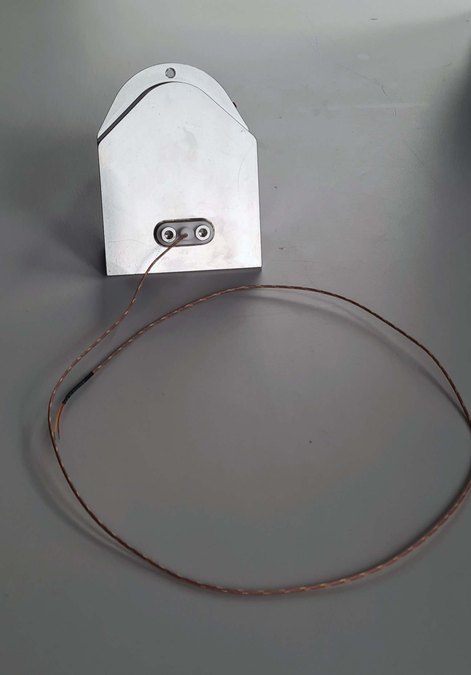
The finished assembled inlet temperature part.
Additional tools needed
2.5-millimeter hexagonal key (L or T-shaped)
Scissors
Slotted screwdriver 2-millimeter
Instructions
before starting - important!
Send an email to support@roestcoffee.com with your order number, production number, and machine name. This information is needed in order to give your machine access to the inlet profiles. Production number and machine name can be found on a sticker at the front of your roaster.

Part 1 - assemble the inlet temperature kit
Unpack the temperature probe. Install the gasket on top of the probe and insert it through the holes in the new housing on the flat side. Push it on until you hear a click. Use the two screws to tighten it into place, but don’t overtighten it as the white piece can break.


part 2 - install the inlet temperature
2. Remove the right-hand side panel.
3. Take off the front décor plate.
4. Only for L100, remove the k-type cable from the PCB. Free the cable from the heater fan.


When you remove the drum temp sensor, leave the connector wide open. The connector on the right is in the correct position, and the connector on the left is in the wrong position.
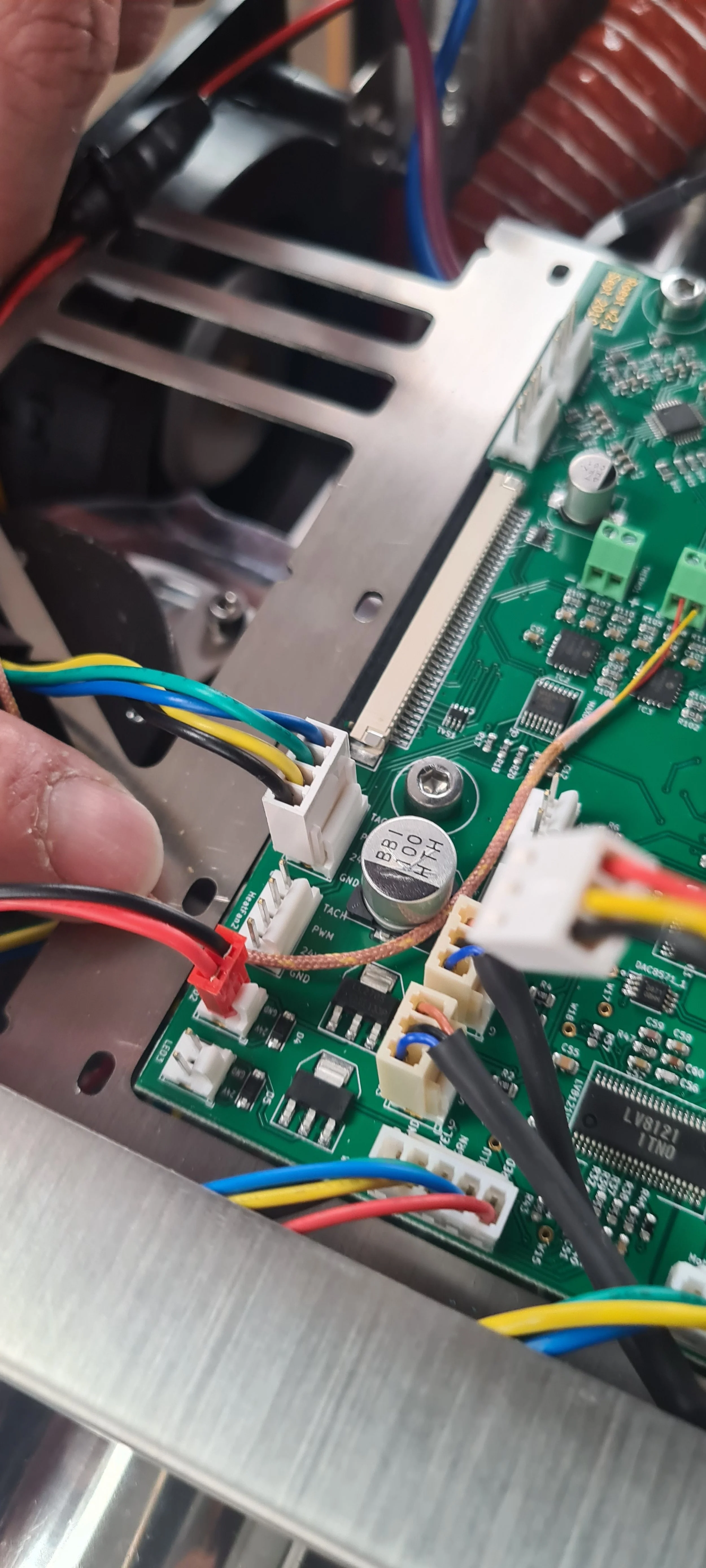
5. Disconnect the heater fan from the PCB and cut the cable ties holding the cables from the heater fan in place.


6. Disconnect the heating element cables from the wago connectors. Undo the two screws on the heating element lid with a 2.5-millimeter hex key, and lift the heating element away from the housing. Put it aside. NOTE: Before disconnecting, take a photo or make a reference to ensure that the correct cable goes into the correct wago connector when reconnecting. Remove the silicone hose.
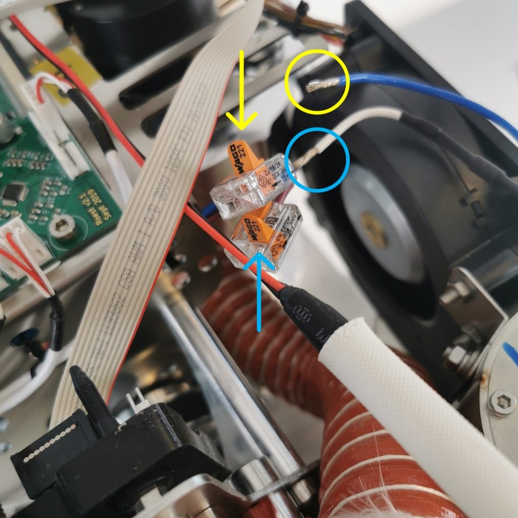
Only open the two flaps that read Wago 221.

7. Remove the six cap head bolts holding the heater fan with the 3-millimeter hexagonal tool.


8. Remove the old heater fan assembly. To do this safely and correctly, follow these steps:

1. Push the heating element housing towards the drum (this will tilt the assembly at approximately 45˚).

2. Pull the heater fan assembly out while maintaining the 45˚ angle. Pull the drum temperature sensor cable out from the holes in the heater fan.
8. Remove the superwool bracket and the superwool.

Superwool and bracket
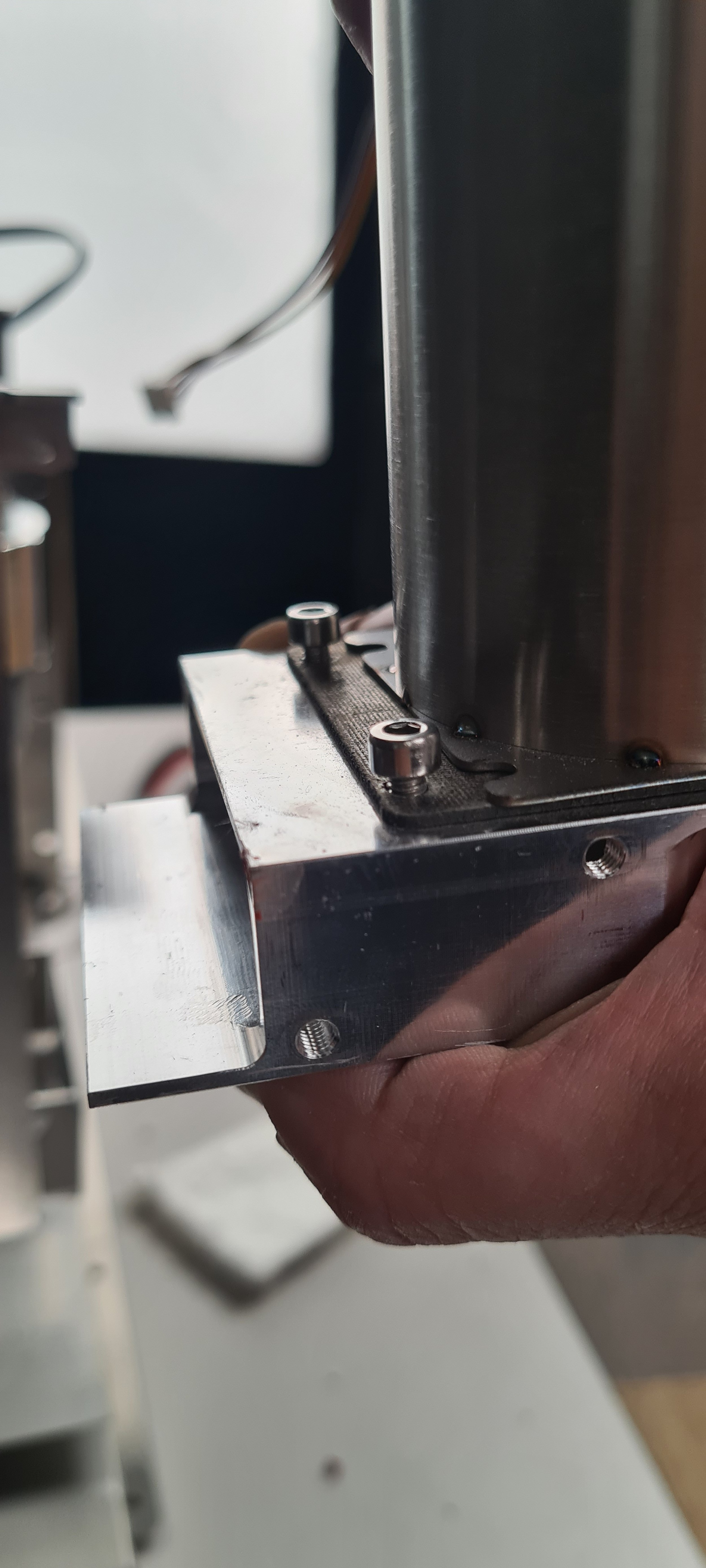
9. Remove the heating element housing from the heater fan by loosening the following three screws.

The tool you received with your kit should be long enough to reach this screw.

Leave the bolts loose like this, do not remove them yet.
Slide the housing away from the two front bolts.
Slide the housing away from the two bolts; now, the housing is free to be removed. Lift the housing upwards to remove it.
10. Remove the old inlet housing and install the new one with the inlet temperature.

Remove the mica tube by pulling it out.

Undo the three bolts and remove them.

Remove the spacer from the old inlet housing.

Install the spacer on the new inlet housing by leaving all three screws loosely done.

Leave space between the bolts and the housing.

Slide the heater fan on the new inlet housing, push it forward until the heater fan covers the spacer, and tighten the three screws. Install the mica tube again.
11. Install the heater fan with the new inlet temperature.

Cut the super wool in half.

Slide the inlet temperature probe through the slit while lifting up the superwool.

Slide the heater fan in place.

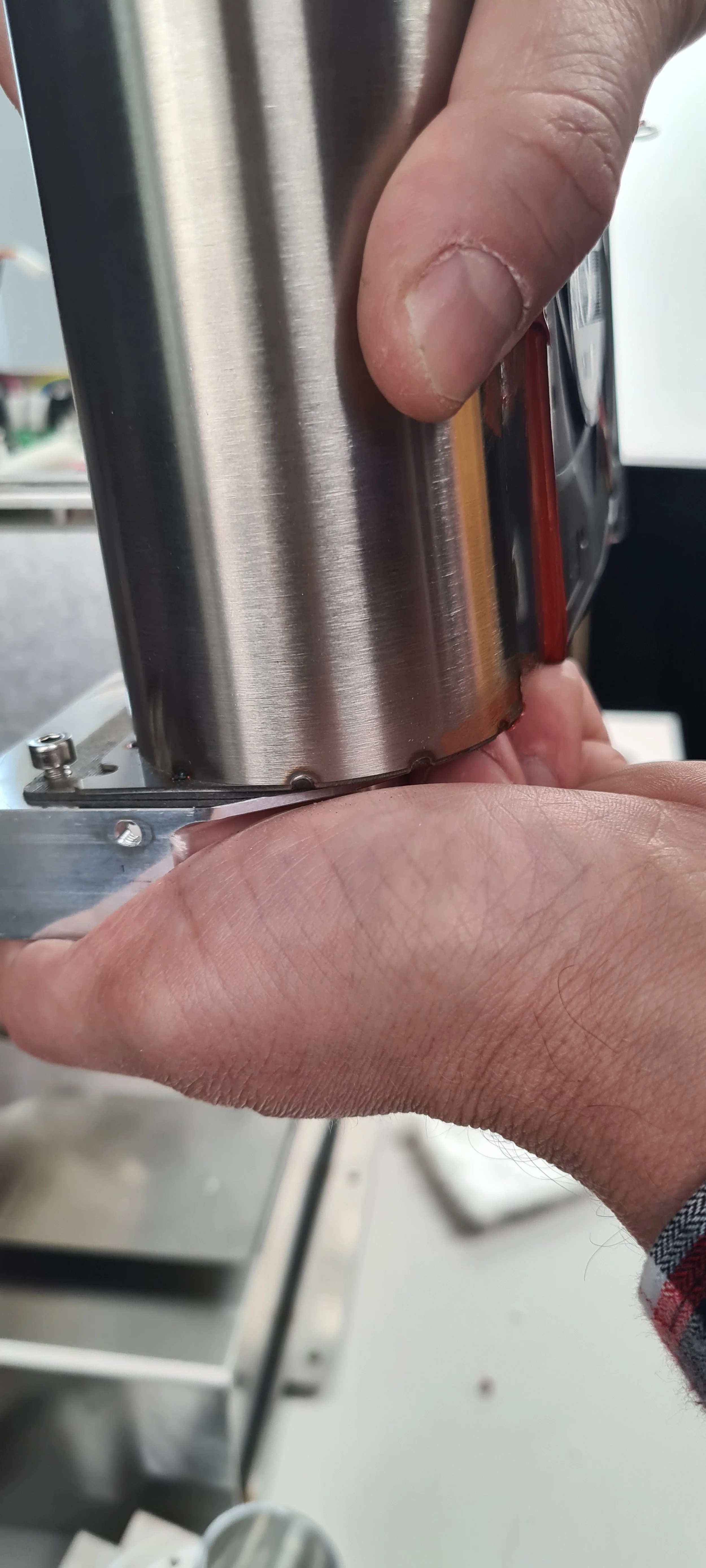
Make sure there is no gap.
Loosely install the six head bolts holding the heater fan in place. With the bolts loose, push the heater fan as close as possible to the drum, then tighten the four outermost bolts. Install the super wool and the bracket, tightening the remaining two bolts. Reinstall the heating element.
Push the bracket down as much as possible and make sure the screws secure the bracket.

Make sure the orientation of the heating element is correct. The red rubber component should be closer to the PCB.
12. Install and connect the cables.

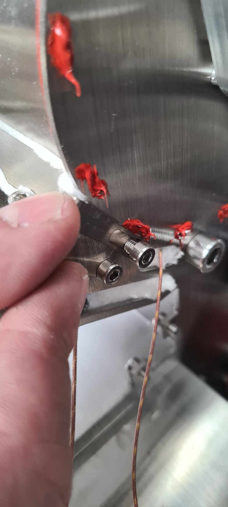
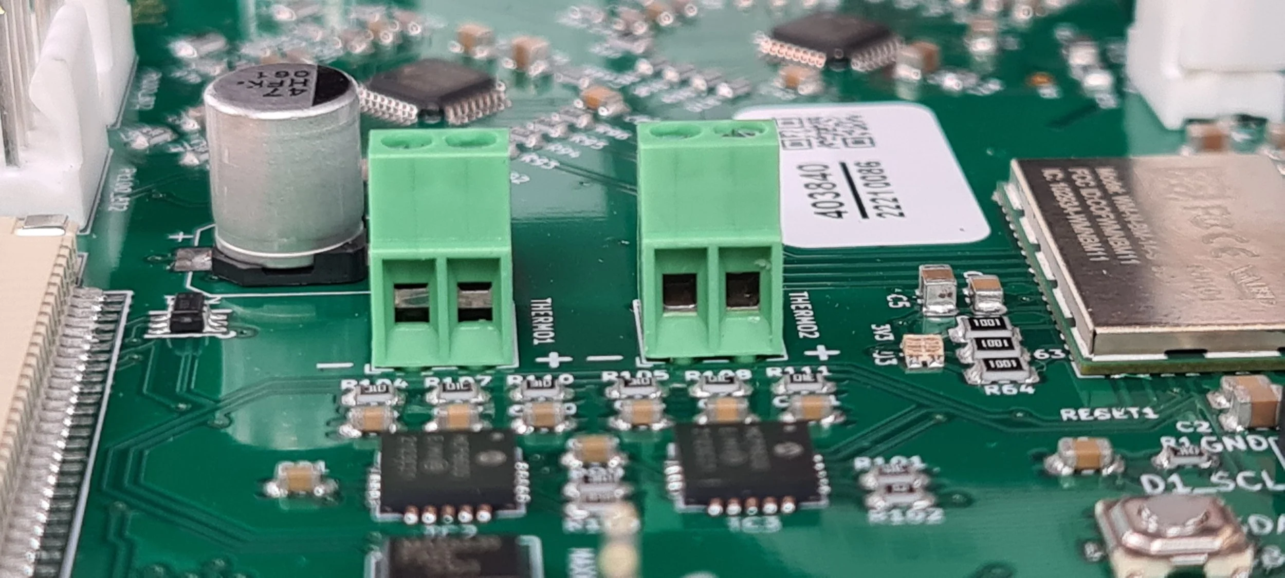
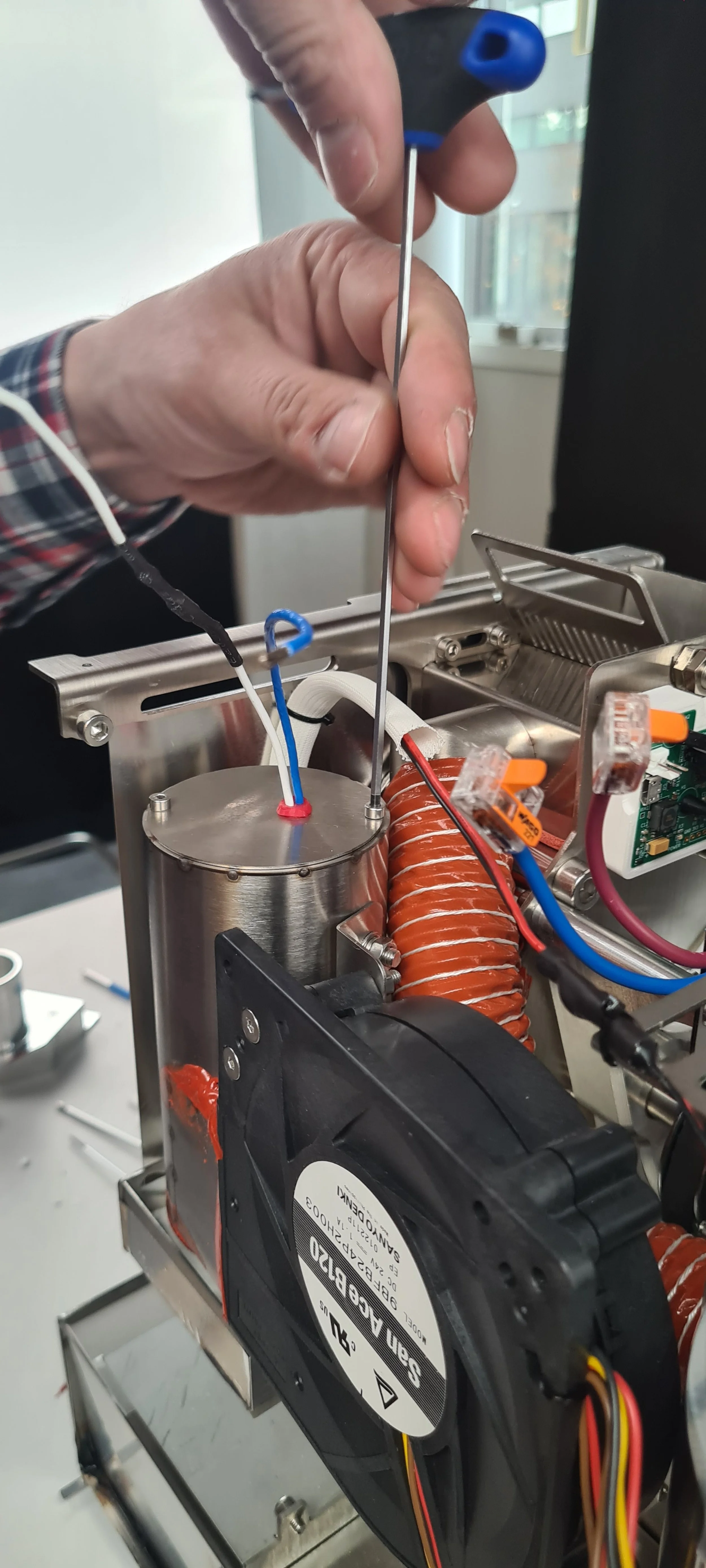
Find the two k-type sensors and pull them out towards you, so they are easily available; the inlet temperature sensor will be marked with black tape so you can easily recognize it.

Pull the drum and inlet sensors through the two holes in the heater fan.

Install the drum and inlet temperature sensors in the screw terminals. Ensure that the drum and inlet are installed into the proper terminals and that the polarity is correct. The right positions are shown in the photo above.
Reconnect the heater fan and the heating element cables (use the reference photo you took at the beginning to ensure they are inserted correctly). Reinstall the orange hose for the exhaust. Use the new cable tie where you cut the cable tie at the beginning of the process.
13. Install the front décor plate. Instructions here.
14. Install the side panels. Find instructions here.
15. Install the top plate following this guide.
You are now ready to use your new inlet temperature sensor!
Video instructions
Having issues?
How to change: Chassis fan
How to change the chassis fan on your ROEST.
Where to buy a chassis fan?
If you are sure your chassis fan is broken (you have talked to our Support Team) visit our e-shop to purchase a new one!
Before you start
⚠️DISCLAIMER
Information in this document is believed to be accurate and reliable. However, the manufacturer does not give any representations or warranties, expressed or implied, as to the accuracy or completeness of such information and shall have no liability for the consequences of the use of such information. The manufacturer is not liable or responsible for any problems arising from the attempted repair. The manufacturer reserves the right to make changes to information published in this document, including without limitation specifications and product descriptions, at any time and without notice. The manufacturer's products are not designed, authorized, or warranted to be suitable for use in applications where failure or malfunction can reasonably be expected to result in personal injury, death, or severe property or environmental damage. The manufacturer accepts no liability for inclusion and/or use of its products in such equipment or applications and therefore such inclusion and/or use is for the customer’s own risk.
⚠️SAFETY INSTRUCTIONS
make sure the roaster is turned off
the power cord has to be unplugged
follow the steps as instructed below
Tools

Cutters

Philips screwdriver
Parts

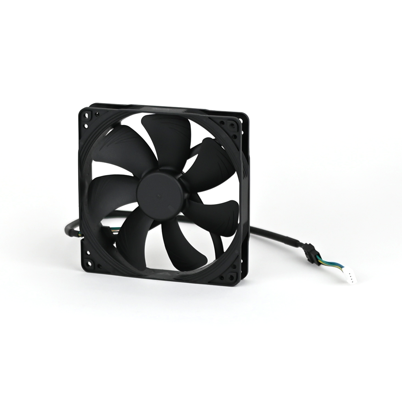
Chassis fan

Cable ties
Instructions
2. Remove the left side panel.
3. Disconnect the connector from PCB and the extension cable from the fan cable. NOTE: the extension cable can be reused for the replacement fan.
4. Cut any cable ties fastening the cable to the roaster.
5. Pull the cable through, so it is loose and hanging from the roaster.
6. Take a photo/reference of the orientation of the ventilation fan before removal. NOTE: fan is meant to draw air into the roaster to keep components cool.

The correct orientation of the fan is shown in the image on the left, seen from the inside of the roaster.
7. Orientate the roaster, so the back is facing you.
8. Using the Phillips screwdriver bit, remove the four fourscrews holding the fan in place.

NOTE: Screws have split washers on them, please take care not to lose them!
9. Remove the old ventilation fan.

10. Locate the new fan in the correct orientation.

11. Fasten all four bolts until tight.

Align holes on the fan with holes on the back of the roaster before installing bolts
12. Feed cable over the top of the chaff separator.
13. Attach extension cable to fan connector.
14. Attach the connector to PCB.
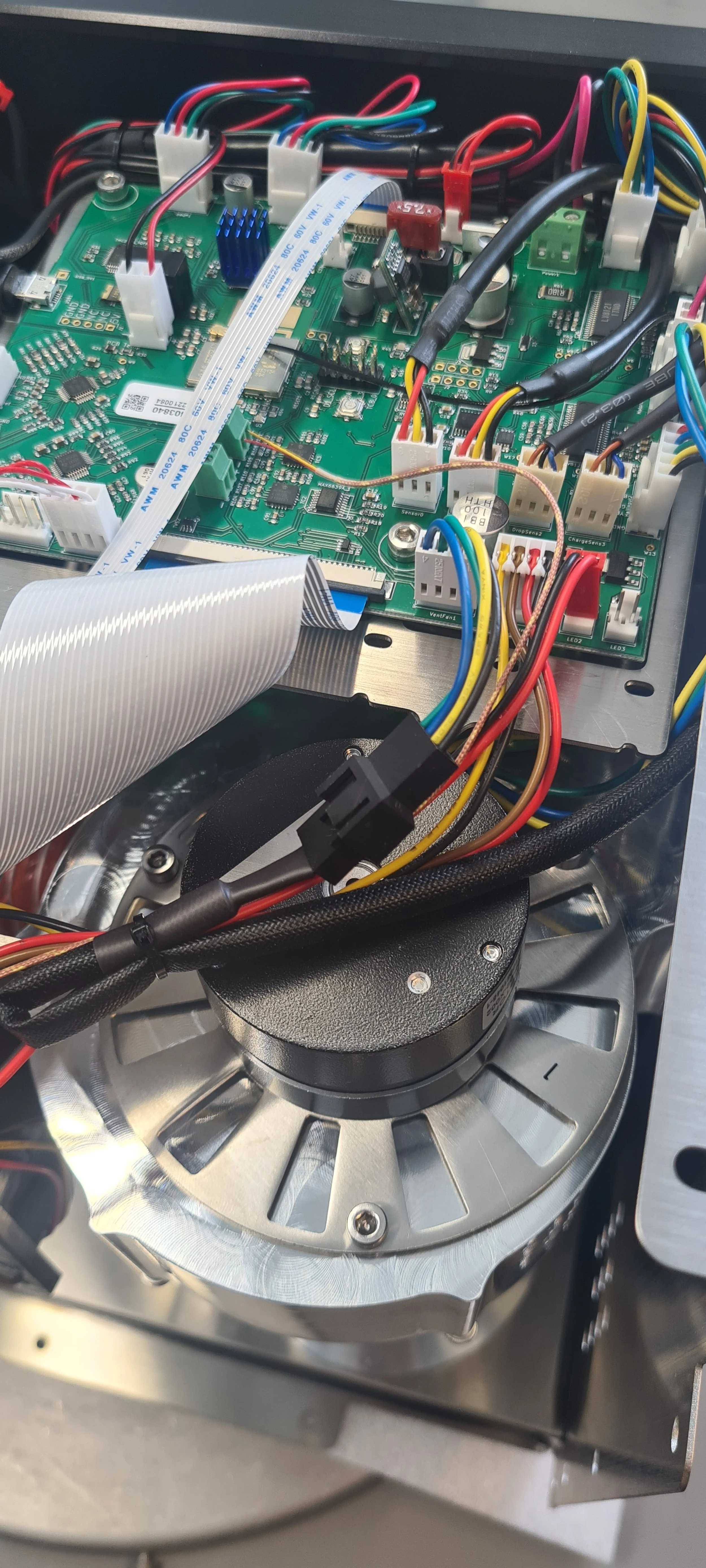
NOTE: PCB reads “VentFan1”
15. Fasten any loose cables to the roaster.
16. Install the left side panel.
18. Plug the roaster in, turn it on and test the chassis fan. If it doesn’t work, contact the ROEST support team.
How to change: Heater fan
How to change the heater fan on your ROEST.
Where to buy heater fan?
If you are sure your heater fan is broken (you have talked to our Support Team) visit our e-shop to purchase a new one!
Before you start
⚠️DISCLAIMER
Information in this document is believed to be accurate and reliable. However, the manufacturer does not give any representations or warranties, expressed or implied, as to the accuracy or completeness of such information and shall have no liability for the consequences of the use of such information. The manufacturer is not liable or responsible for any problems arising from the attempted repair. The manufacturer reserves the right to make changes to information published in this document, including without limitation specifications and product descriptions, at any time and without notice. The manufacturer's products are not designed, authorized, or warranted to be suitable for use in applications where failure or malfunction can reasonably be expected to result in personal injury, death, or severe property or environmental damage. The manufacturer accepts no liability for inclusion and/or use of its products in such equipment or applications and therefore such inclusion and/or use is for the customer’s own risk.
⚠️SAFETY INSTRUCTIONS
make sure the roaster is turned off
the power cord has to be unplugged
follow the steps as instructed below
Tools
2.5-millimeter hexagonal key (L or T-shaped)
3-millimeter hexagonal key (T-shaped, long)
Stanley knife
Plastic gloves
Parts


NOTE: PCB reads “HeatFan2”
Disconnect the drum and inlet temperature sensor. This procedure is the same for both sensors.

Note how the wires are inserted into the screw terminal, the yellow wire is positive, and the red wire is negative.
Make sure you open the hole up, as done on the right terminal. The left terminal is in the incorrect position.

Pull the cable through the holes in the heater fan.

Remove the cable completely from the heater fan.
5. Disconnect heating element cables from wago connectors and cut the cable ties. NOTE: Before disconnecting, take a photo or make a reference to ensure that the correct cable goes into the correct wago connector when reconnecting.

Cut the cable ties holding the cables from the heater fan in place. If you have extra, note how the cables are tied, so you can tie them up again when finished.
Only open the two flaps that read Wago 221.
6. Remove the heating system.
Undo the two bolts for the heating element.

Remove the heating element.

Undo one bolt loosely (don’t remove) on the inside of the heating element housing.

Undo two bolts loosely on the outside of the heating element housing, but don’t remove them. You can remove the orange hose to see better.

If you look inside the housing, it should look like this.

Pull the housing backward, so it slides away from the bolts holding it.

Pull the heating element housing with the heater fan upwards.

What it should look like after you pulled the housing off.
7. Install the new heater fan onto the old heating element housing.

The heating system you removed from the roaster should look like this.

Undo these two screws using a 2.5-millimeter hexagonal key. Hold a finger or on the back to keep the screw from spinning.

Use a spanner to hold the nut in place.

Use the spanner on the nut while undoing the screw from the other side.
Save your screws and nuts from the old heater fan; you will need them for the new one.

Cut the silicone on all sides where the fan and housing meet.

Pull the fan and housing apart.

Your old heater fan should be separated from the heating element housing at this point.

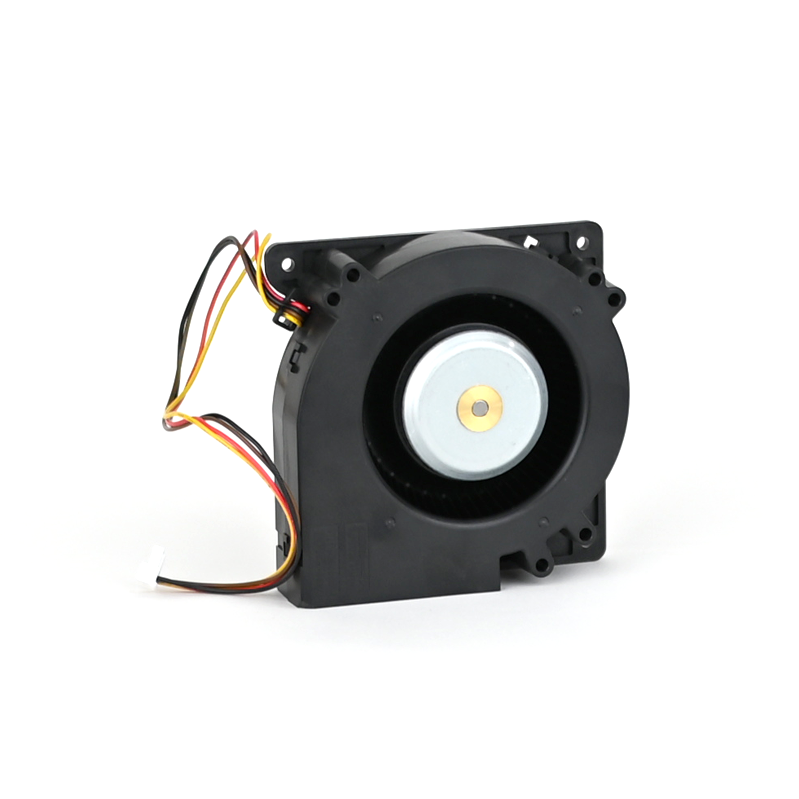
Find your new heater fan.

The orientation of the heater fan in relation to the heating element housing should be as shown in the photo above. There is a slot in the heater fan where the housing can be inserted.

Slide the housing inside the heater fan.

Insert the screws you removed from the old fan.

Turn your fan around (watch the screws so they don’t fall out).

Place the washers.

Place the nuts.

Find your spanner again to tighten the nuts.

Tighten the screws.

You need to use both your spanner and hexagonal key simultaneously.

You will need some silicone. We should provide it if you purchased a heater fan in our webshop.

You will need plastic gloves as well. Cut a hole at the tip of the bag to make a piping bag.

Use the piping bag to add silicone where the heater fan meets the heating element housing.

Add silicone to all sides.


Smear it out with your finger, removing excess silicone.


Make sure the area around the heating element stays clean.
8. Wait 24 hours for the silicone to dry.
9. Install the new heater fan system onto the roaster.

Slide the heating system onto the inlet housing.

Then push the heating system into place.

When your system has slid into place, it will look like this inside. If your mica tube is in the way, you can remove it.

Tighten the bolt inside and the two bolts on the outside. Install the mica tube if you removed it.
10. Install the heating element and connect it to the correct wago connectors (look at the image at the beginning of the guide for reference). Use a 2.5-millimeter hexagonal key to tighten the bolts.


Note the orientation of the heating element. The red rubber component should be closer to the PCB.
11. Install the drum and inlet temperature sensors if you have them:

Pull the cable through the bottom hole.

And then pull it through the top hole again.

Pull it through all the way, but not too tightly.

Make a note of the colors of the wires: Yellow is positive, and red is negative.

Make a note of the orientation on the terminal. Ensure the yellow wire goes into the positive terminal and the red wire goes into the negative terminal.
Ensure the cable is not in the way or hanging too loosely in the machine.
Do the same for the inlet temperature; insert it into the left screw terminal instead.
12. Connect the heater fan to the PCB (refer to the beginning of this guide if you are unsure of where).
13. Install back the front décor plate. Instructions here.
14. Install back the side panels. Find instructions here.
15. Install back the top plate following this guide.
16. Plug the roaster in, turn it on and test the heater fan. If it doesn’t work, contact the ROEST support team.
-
Adjustable roasting parameters
Service menu - includes recommended settings for motor gear ratio, cooling fan, heater fan, and PID settings.
-