
How to change: Exhaust temperature sensor
How to change the exhaust temperature sensor on your ROEST.

Where to buy temperature sensors?
If you are sure that a temperature sensor in your roaster is broken (you have talked to our Support Team) visit our e-shop to purchase a new one! The exhaust sensor uses the same probe as the BT sensor.
Before you start
⚠️DISCLAIMER
Information in this document is believed to be accurate and reliable. However, the manufacturer does not give any representations or warranties, expressed or implied, as to the accuracy or completeness of such information and shall have no liability for the consequences of the use of such information. The manufacturer is not liable or responsible for any problems arising from the attempted repair. The manufacturer reserves the right to make changes to information published in this document, including without limitation specifications and product descriptions, at any time and without notice. The manufacturer's products are not designed, authorized, or warranted to be suitable for use in applications where failure or malfunction can reasonably be expected to result in personal injury, death, or severe property or environmental damage. The manufacturer accepts no liability for inclusion and/or use of its products in such equipment or applications and therefore such inclusion and/or use is for the customer’s own risk.
⚠️SAFETY INSTRUCTIONS
make sure the roaster is turned off
the power cord has to be unplugged
follow the steps as instructed below
Tools

10-millimeter wrench

Cutters
Parts

Exhaust temperature sensor

Cable ties

Tray, or similar, to keep removed components
Instructions
Follow this numbered guide below step by step.
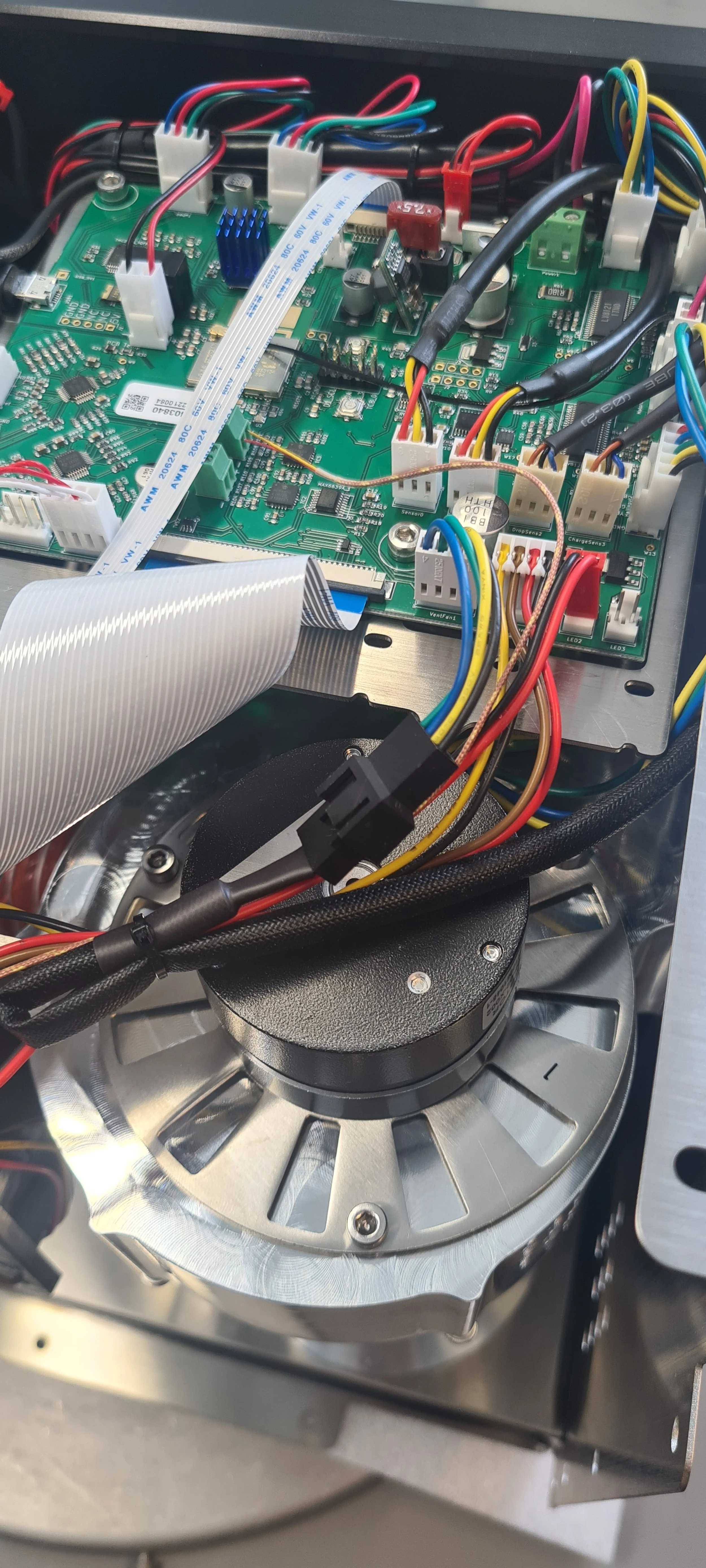
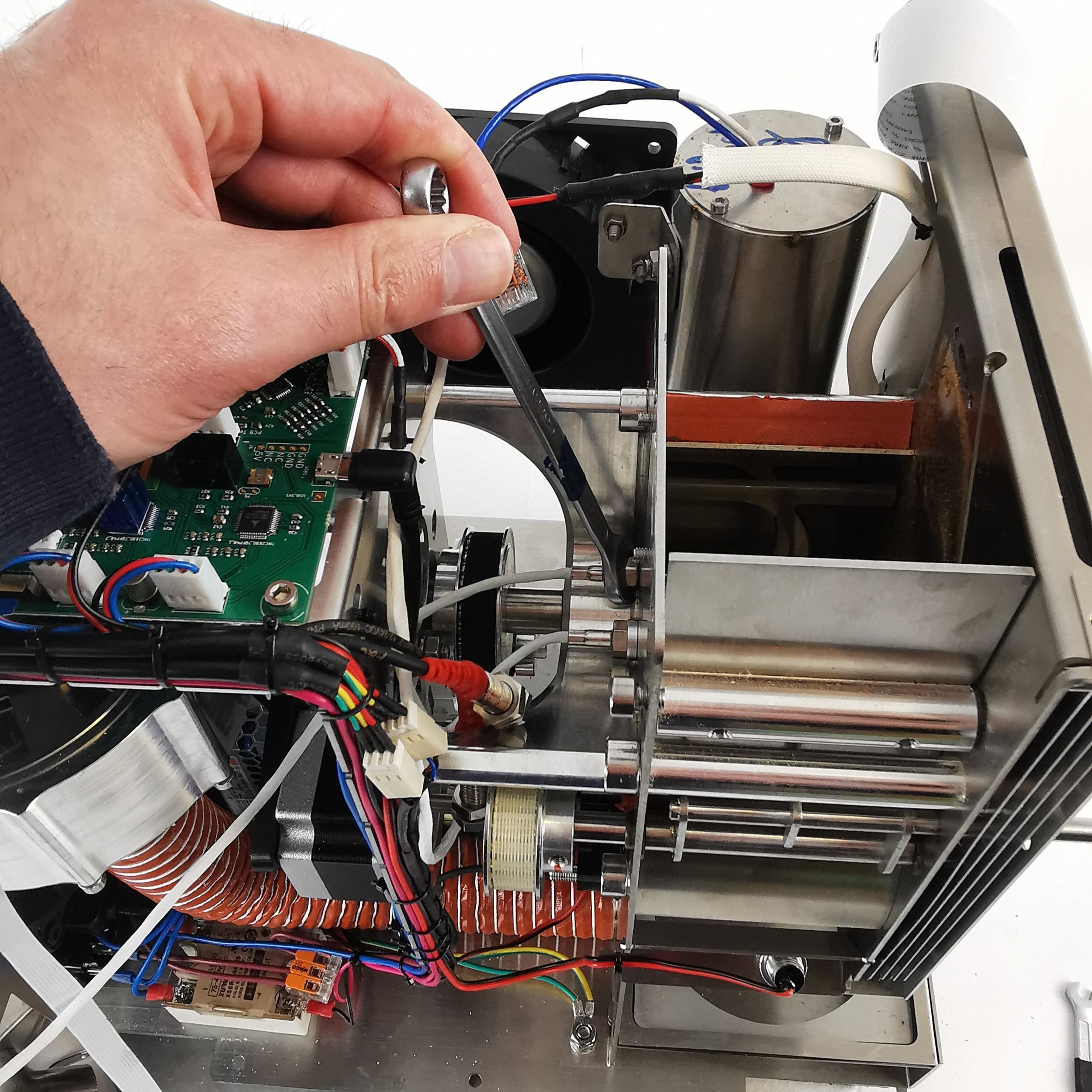
3. If your roaster has First Crack detection, you can optionally remove it for easier access. To do so, pull the card gently off the rubber mounts. Leave the cable connected and place the card to one side.

4. Unplug the Exhaust Temperature sensor from the PCB.
5. Cut the cable ties holding the cable in place.
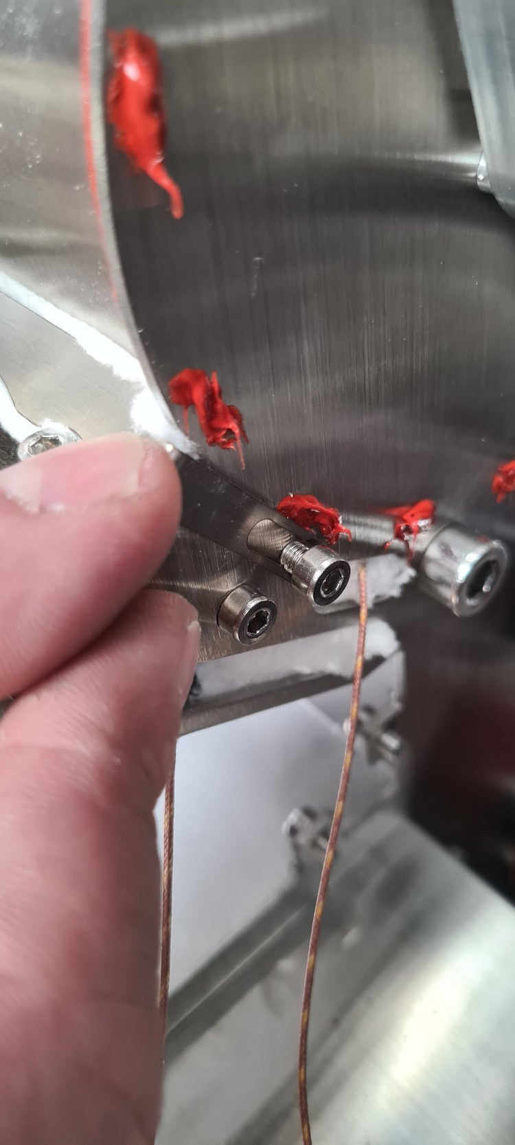
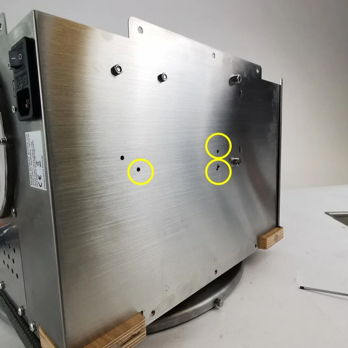
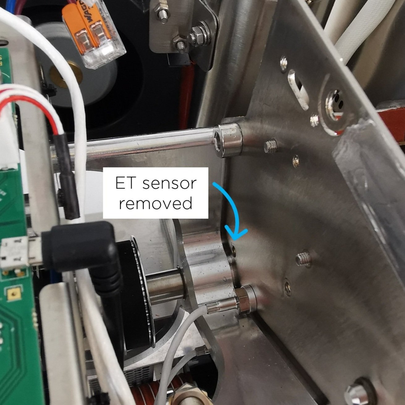
6. Use a 10-millimeter spanner/wrench to loosen the exhaust sensor, and unscrew the sensor from the drum to remove it.
7. Take off the aluminum spacer from the old sensor, and replace it on the new sensor.

8. Screw the new sensor into the back plate by hand until finger tight. NOTE: Please ensure no resistance when rotating so as not to damage the thread in the back plate.
9. Tighten gently with a 10-millimeter wrench. Do not overtighten, as this can strip the thread and scrap the back plate.
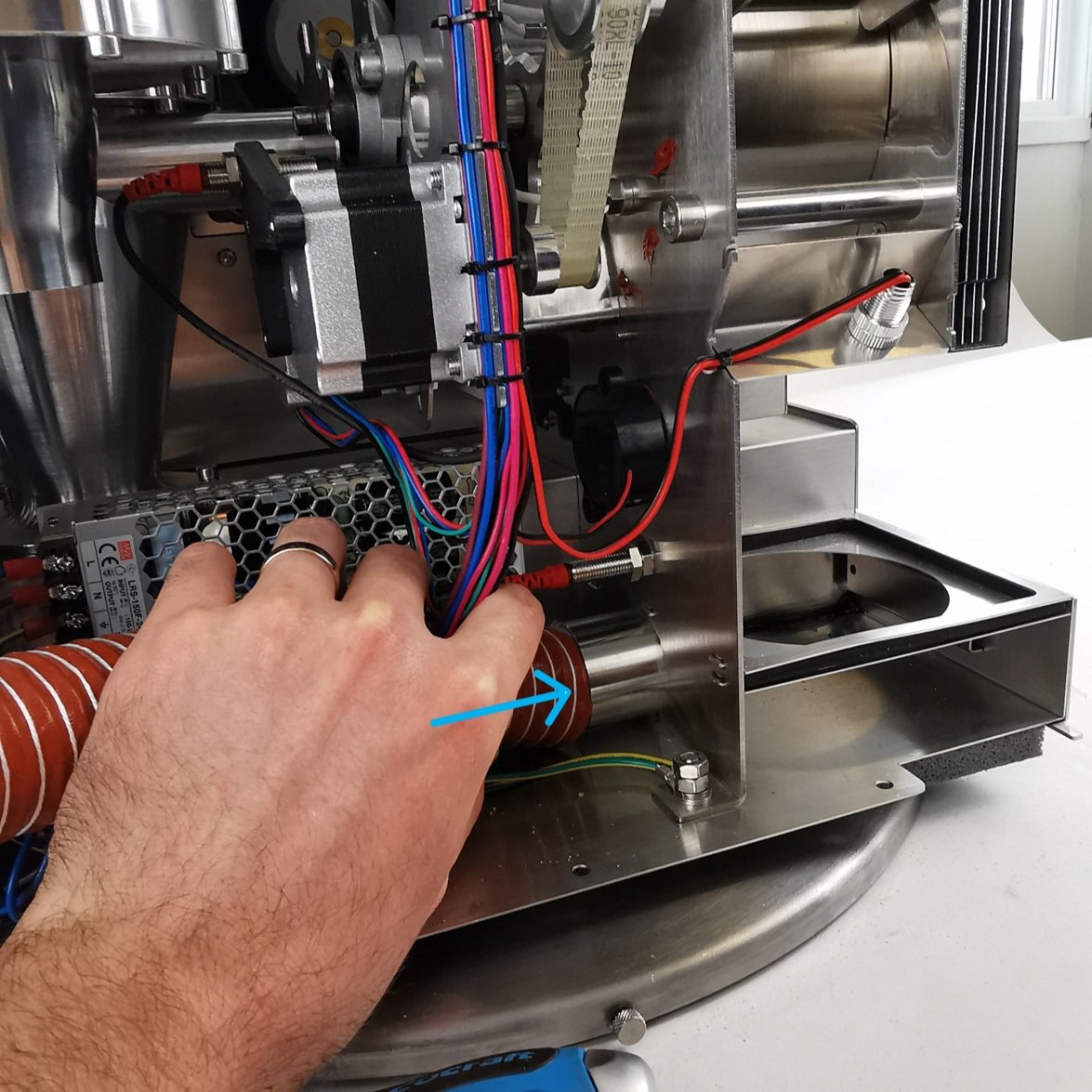
10. Feed the cable from the new sensor into position. Pass the cable alongside the other white sensor cables, behind the USB cable, then connect it to the PCB.
11. Tie two new cable ties to the motor bracket where you removed the cable ties earlier.
NOTE: Cable should not touch rotating pulley. This can damage/destroy the sensor over time.
Use cutters to trim excess ends on cable ties.
12. Re-install FC card.

a. Push FC card into position. Pull gently on the ends of the rubber mounts to secure them in place.

b. First Crack card should NOT touch the back plate of the roaster.
24. Install side panels.
26. Plug the roaster in, turn it on and test the exhaust temperature sensor by starting a roast (beans in the machine). You should see the exhaust temperature appear on the graph in live view. If the exhaust temperature doesn’t appear, please double-check the connection to the PCB, and then contact the ROEST support team for help.
How to install: Inlet temperature sensor
How to install the inlet temperature sensor on your ROEST.
Sections:
Where to buy an inlet temperature sensor?
Read here on how to purchase an inlet temperature sensor for your roaster.
Before you start
⚠️DISCLAIMER
Information in this document is believed to be accurate and reliable. However, the manufacturer does not give any representations or warranties, expressed or implied, as to the accuracy or completeness of such information and shall have no liability for the consequences of the use of such information. The manufacturer is not liable or responsible for any problems arising from the attempted repair. The manufacturer reserves the right to make changes to information published in this document, including without limitation specifications and product descriptions, at any time and without notice. The manufacturer's products are not designed, authorized, or warranted to be suitable for use in applications where failure or malfunction can reasonably be expected to result in personal injury, death, or severe property or environmental damage. The manufacturer accepts no liability for inclusion and/or use of its products in such equipment or applications, and therefore such inclusion and/or use is for the customer’s own risk.
⚠️SAFETY INSTRUCTIONS
make sure the roaster is turned off
the power cord has to be unplugged
follow the steps as instructed below
Included parts

Inlet temperature kit: new heating element housing, inlet temperature probe, gasket, two screws, cable ties and 3-millimeter hexagonal key (long L-shaped)
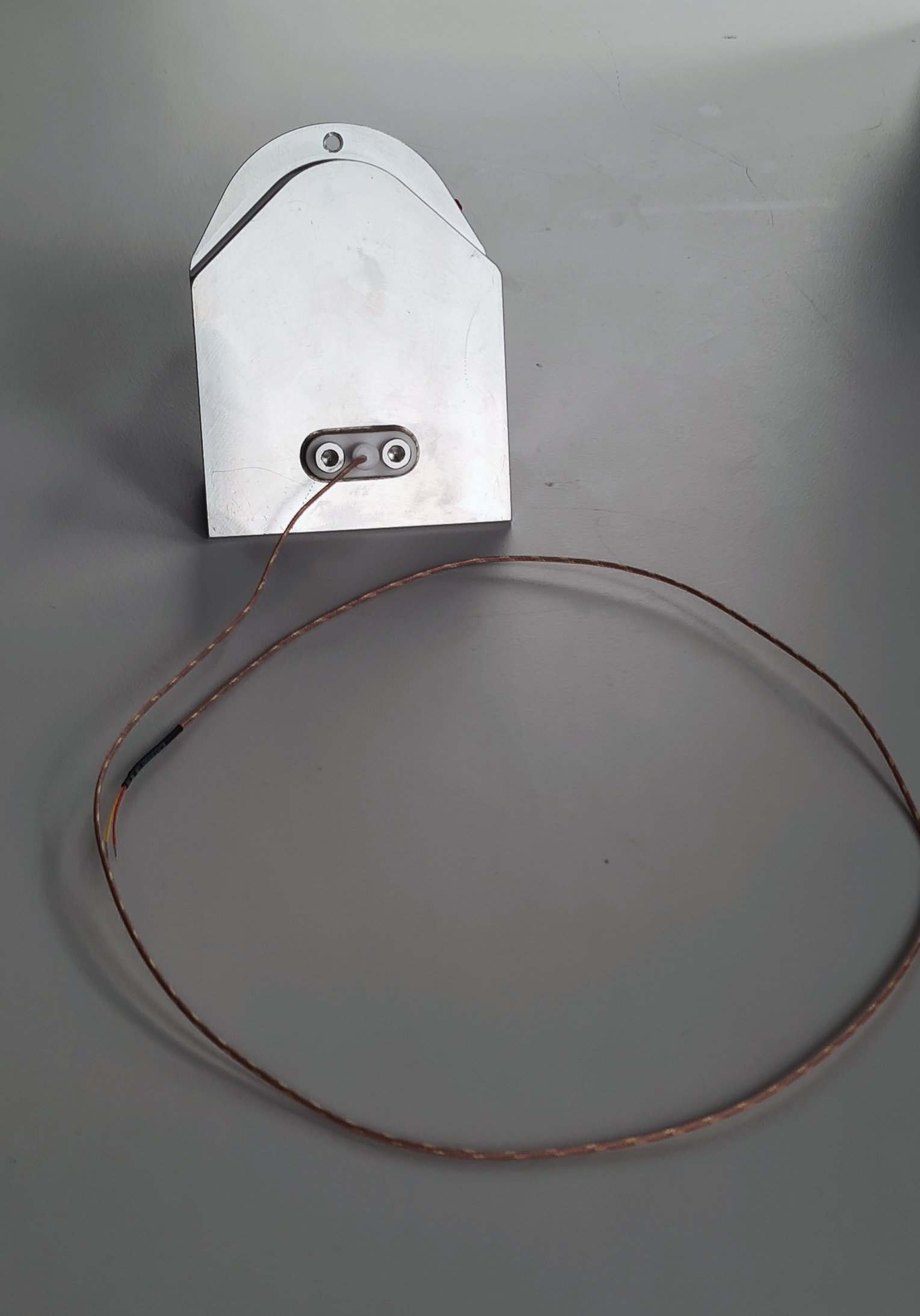
The finished assembled inlet temperature part.
Additional tools needed
2.5-millimeter hexagonal key (L or T-shaped)
Scissors
Slotted screwdriver 2-millimeter
Instructions
before starting - important!
Send an email to support@roestcoffee.com with your order number, production number, and machine name. This information is needed in order to give your machine access to the inlet profiles. Production number and machine name can be found on a sticker at the front of your roaster.

Part 1 - assemble the inlet temperature kit
Unpack the temperature probe. Install the gasket on top of the probe and insert it through the holes in the new housing on the flat side. Push it on until you hear a click. Use the two screws to tighten it into place, but don’t overtighten it as the white piece can break.


part 2 - install the inlet temperature
2. Remove the right-hand side panel.
3. Take off the front décor plate.
4. Only for L100, remove the k-type cable from the PCB. Free the cable from the heater fan.


When you remove the drum temp sensor, leave the connector wide open. The connector on the right is in the correct position, and the connector on the left is in the wrong position.
5. Disconnect the heater fan from the PCB and cut the cable ties holding the cables from the heater fan in place.


6. Disconnect the heating element cables from the wago connectors. Undo the two screws on the heating element lid with a 2.5-millimeter hex key, and lift the heating element away from the housing. Put it aside. NOTE: Before disconnecting, take a photo or make a reference to ensure that the correct cable goes into the correct wago connector when reconnecting. Remove the silicone hose.
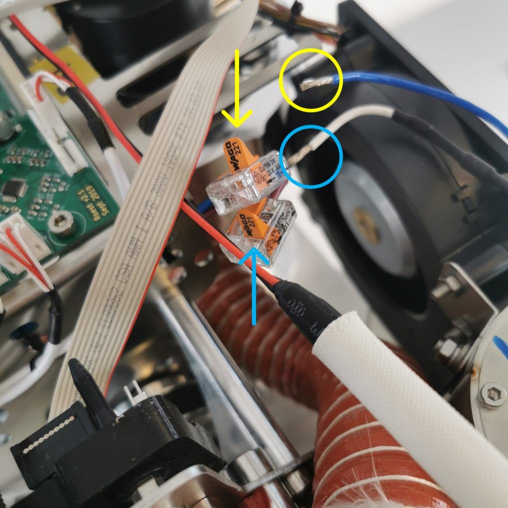
Only open the two flaps that read Wago 221.

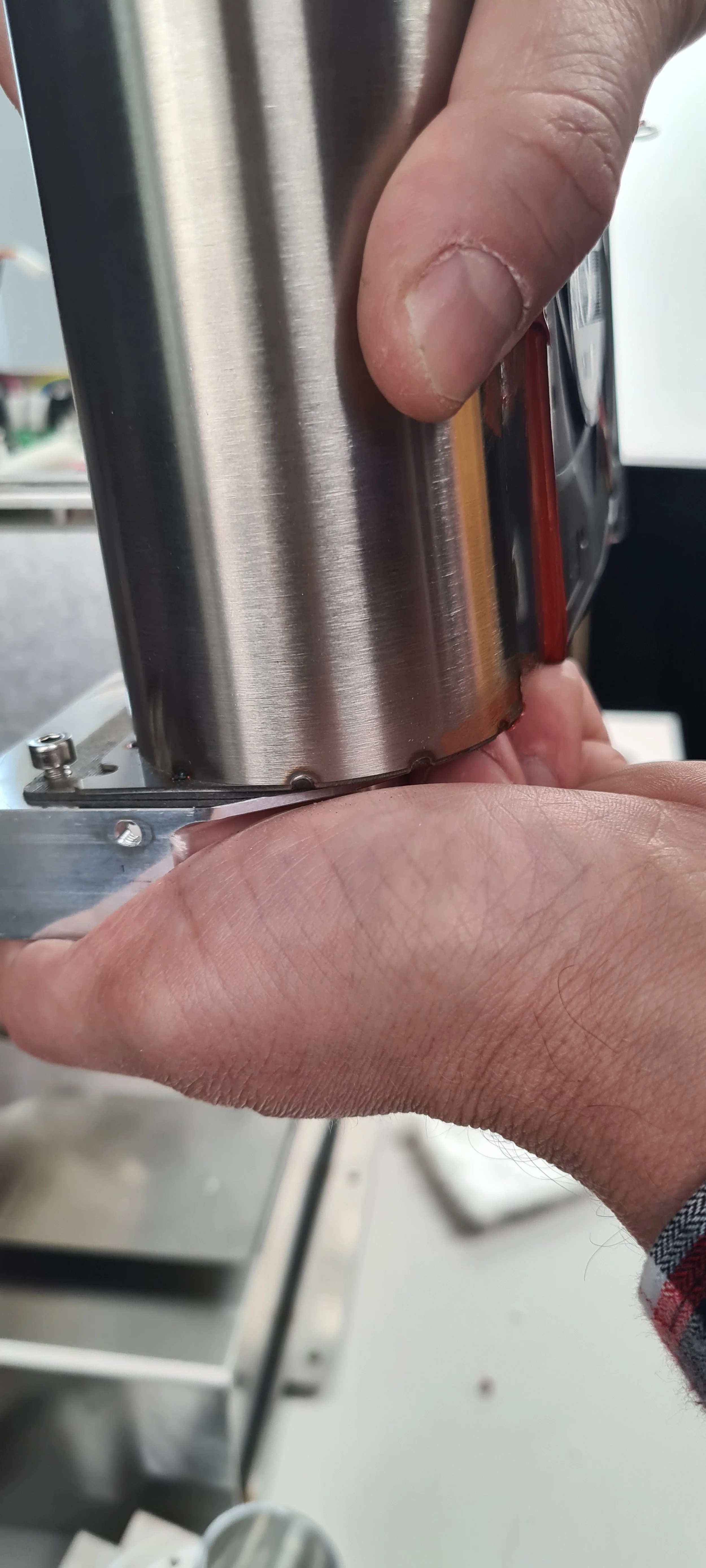
7. Remove the six cap head bolts holding the heater fan with the 3-millimeter hexagonal tool.


8. Remove the old heater fan assembly. To do this safely and correctly, follow these steps:

1. Push the heating element housing towards the drum (this will tilt the assembly at approximately 45˚).

2. Pull the heater fan assembly out while maintaining the 45˚ angle. Pull the drum temperature sensor cable out from the holes in the heater fan.
8. Remove the superwool bracket and the superwool.

Superwool and bracket
9. Remove the heating element housing from the heater fan by loosening the following three screws.

The tool you received with your kit should be long enough to reach this screw.

Leave the bolts loose like this, do not remove them yet.
Slide the housing away from the two front bolts.
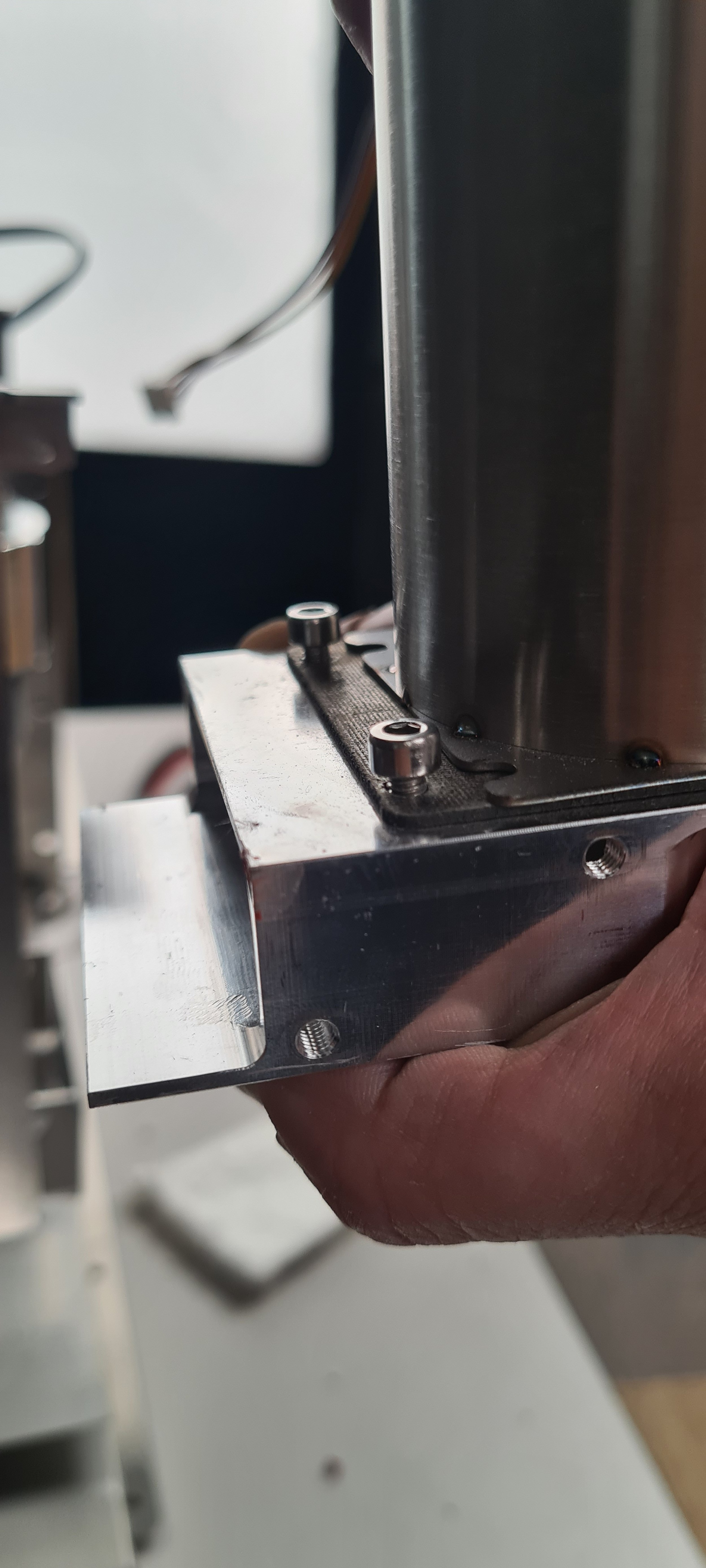
Slide the housing away from the two bolts; now, the housing is free to be removed. Lift the housing upwards to remove it.
10. Remove the old inlet housing and install the new one with the inlet temperature.

Remove the mica tube by pulling it out.

Undo the three bolts and remove them.

Remove the spacer from the old inlet housing.

Install the spacer on the new inlet housing by leaving all three screws loosely done.

Leave space between the bolts and the housing.

Slide the heater fan on the new inlet housing, push it forward until the heater fan covers the spacer, and tighten the three screws. Install the mica tube again.
11. Install the heater fan with the new inlet temperature.

Cut the super wool in half.

Slide the inlet temperature probe through the slit while lifting up the superwool.

Slide the heater fan in place.

Make sure there is no gap.
Loosely install the six head bolts holding the heater fan in place. With the bolts loose, push the heater fan as close as possible to the drum, then tighten the four outermost bolts. Install the super wool and the bracket, tightening the remaining two bolts. Reinstall the heating element.
Push the bracket down as much as possible and make sure the screws secure the bracket.

Make sure the orientation of the heating element is correct. The red rubber component should be closer to the PCB.
12. Install and connect the cables.

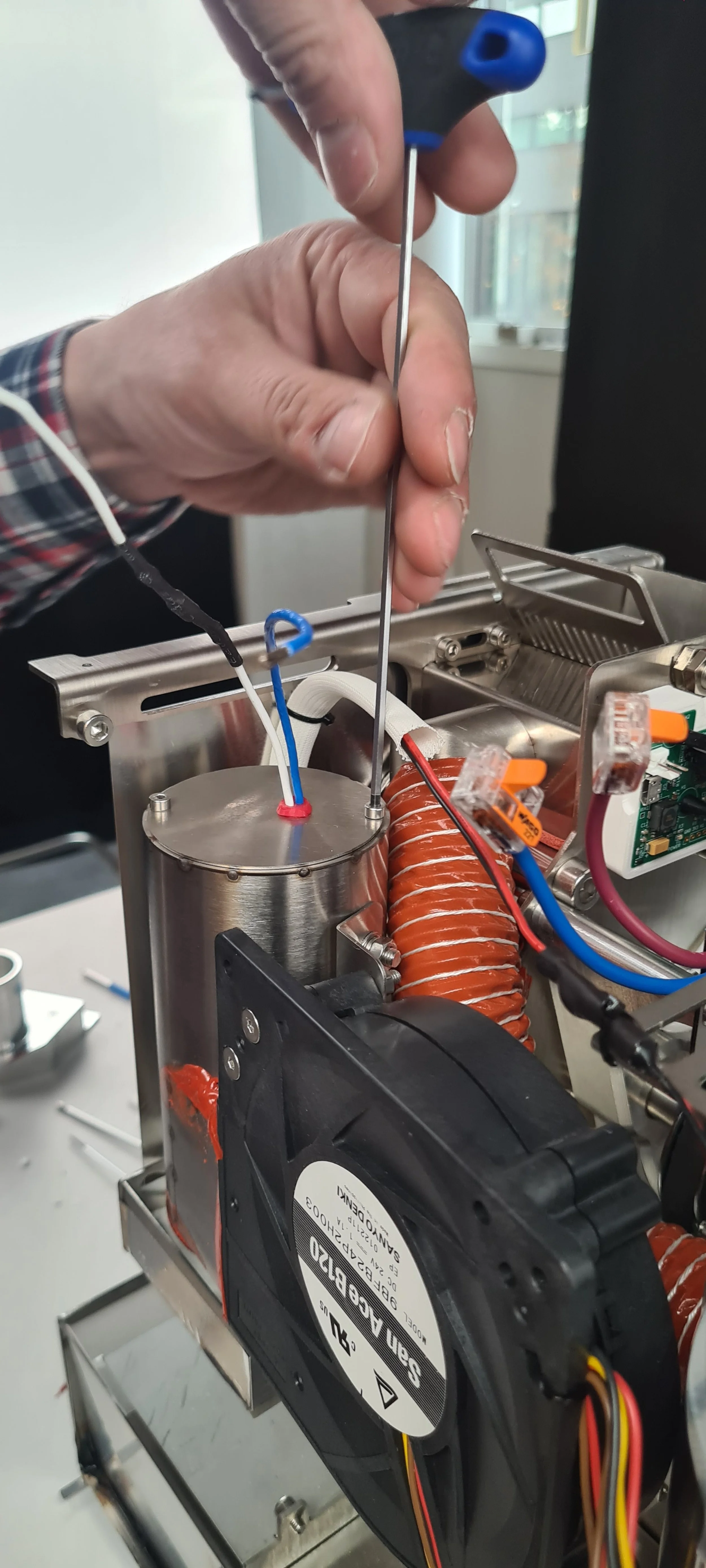
Find the two k-type sensors and pull them out towards you, so they are easily available; the inlet temperature sensor will be marked with black tape so you can easily recognize it.

Pull the drum and inlet sensors through the two holes in the heater fan.

Install the drum and inlet temperature sensors in the screw terminals. Ensure that the drum and inlet are installed into the proper terminals and that the polarity is correct. The right positions are shown in the photo above.
Reconnect the heater fan and the heating element cables (use the reference photo you took at the beginning to ensure they are inserted correctly). Reinstall the orange hose for the exhaust. Use the new cable tie where you cut the cable tie at the beginning of the process.
13. Install the front décor plate. Instructions here.
14. Install the side panels. Find instructions here.
15. Install the top plate following this guide.
You are now ready to use your new inlet temperature sensor!
Video instructions
Having issues?
PCB overview
Here you can see a complete overview of the PCB.

YELLOW:
Exhaust fan 5 pin connector
Extra LED light/24v output
LED light window
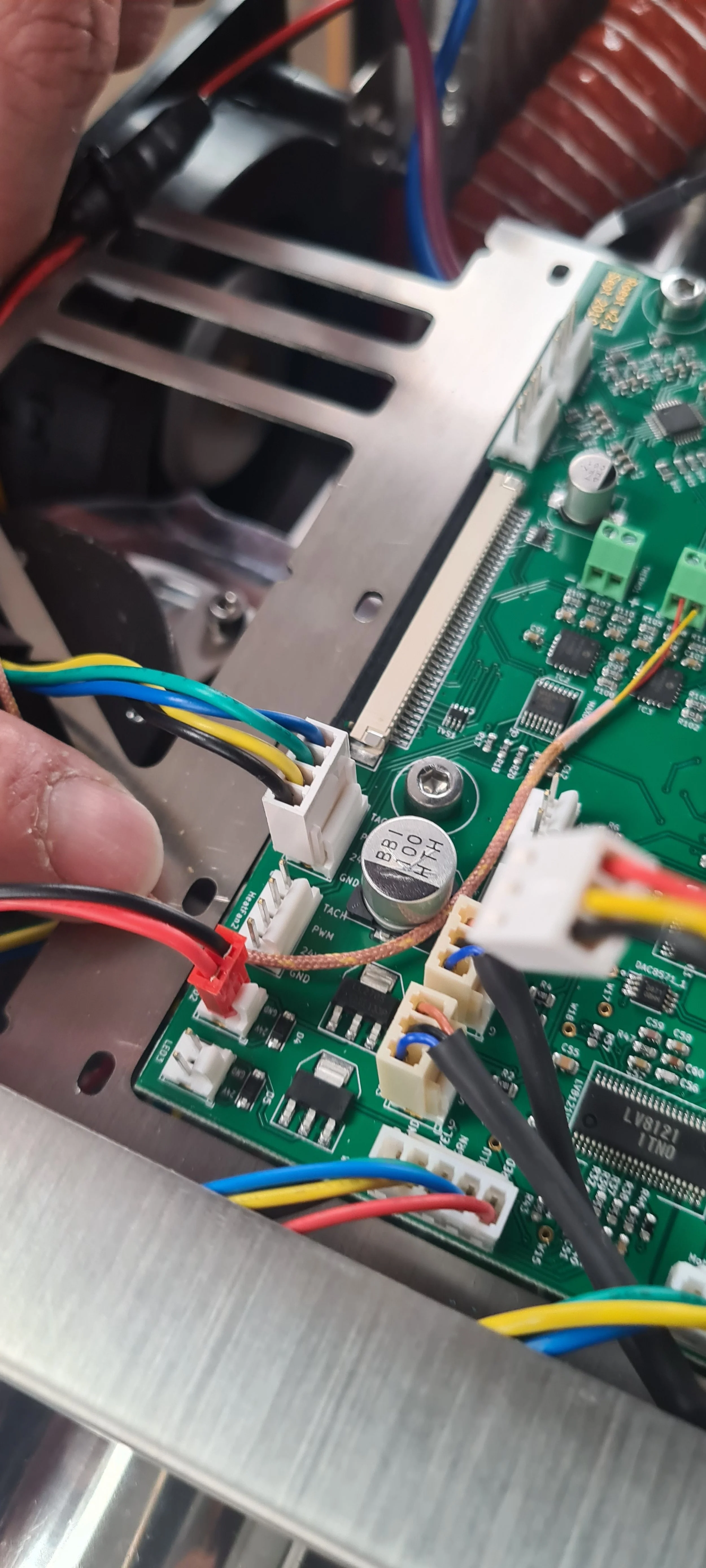
Heater fan
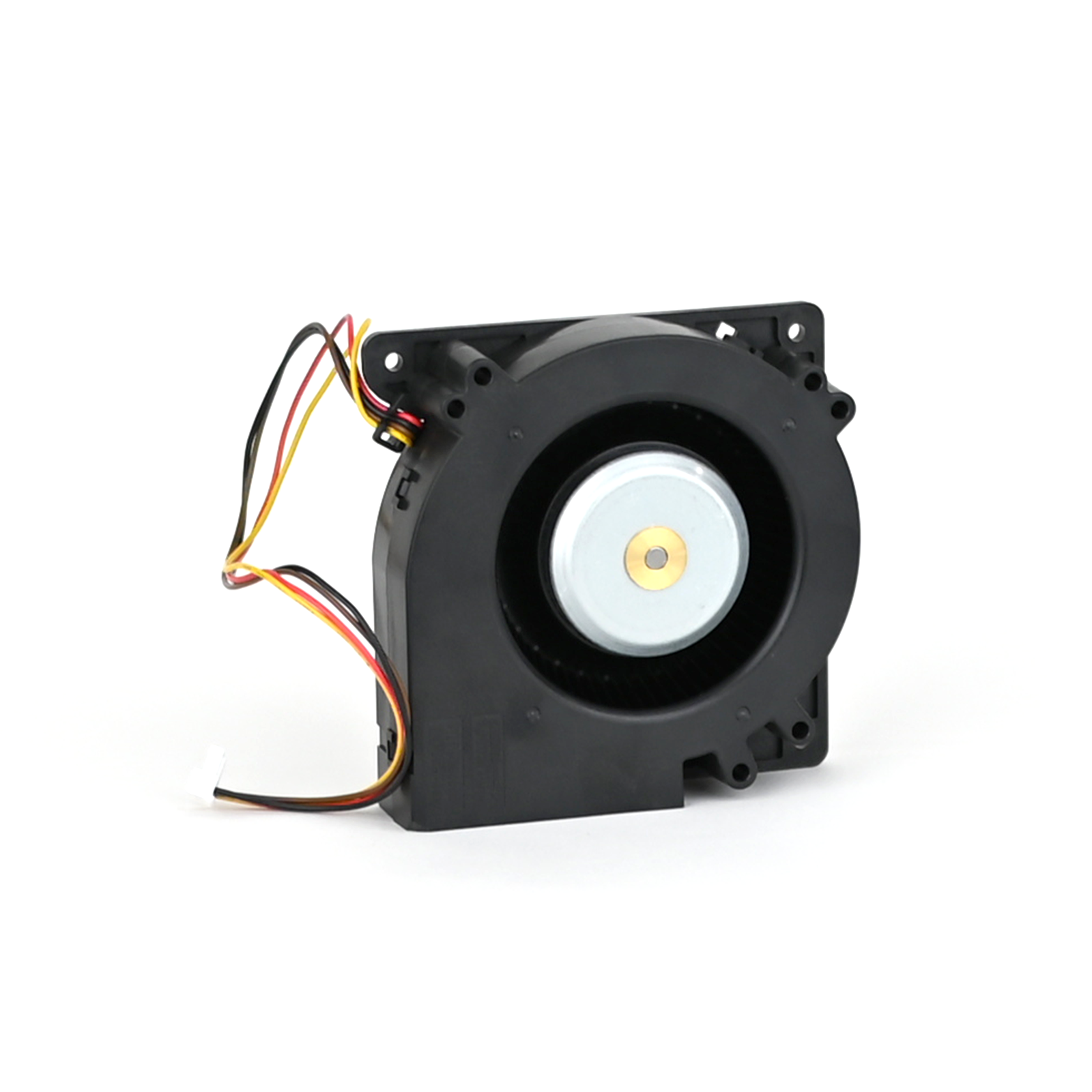
Chassis fan (large computer fan at the back)
Touch screen
Exhaust temperature pt-100
Extra temperature pt-100
Air temperature pt-100
Bean temperature pt-100
RED:
Drop handle sensor
Charge handle sensor
RPM proximity sensor (monitors paddles)
Bean cooler warning sensor
First crack detection
Inlet K-type temperature sensor
Drum K-type temperature sensor
Wi-Fi antenna
Buzzer
BLUE:
Exhaust fan 3 pin connector
Power heating element (Solid state relay)
Bean cooler fan 5 pin connector
Bean cooler fan 3 pin connector
LED light bean cooler
Encoder
Chamber motor
Drop door motor
USB
How to change: Chassis fan
How to change the chassis fan on your ROEST.
Where to buy a chassis fan?
If you are sure your chassis fan is broken (you have talked to our Support Team) visit our e-shop to purchase a new one!
Before you start
⚠️DISCLAIMER
Information in this document is believed to be accurate and reliable. However, the manufacturer does not give any representations or warranties, expressed or implied, as to the accuracy or completeness of such information and shall have no liability for the consequences of the use of such information. The manufacturer is not liable or responsible for any problems arising from the attempted repair. The manufacturer reserves the right to make changes to information published in this document, including without limitation specifications and product descriptions, at any time and without notice. The manufacturer's products are not designed, authorized, or warranted to be suitable for use in applications where failure or malfunction can reasonably be expected to result in personal injury, death, or severe property or environmental damage. The manufacturer accepts no liability for inclusion and/or use of its products in such equipment or applications and therefore such inclusion and/or use is for the customer’s own risk.
⚠️SAFETY INSTRUCTIONS
make sure the roaster is turned off
the power cord has to be unplugged
follow the steps as instructed below
Tools

Cutters

Philips screwdriver
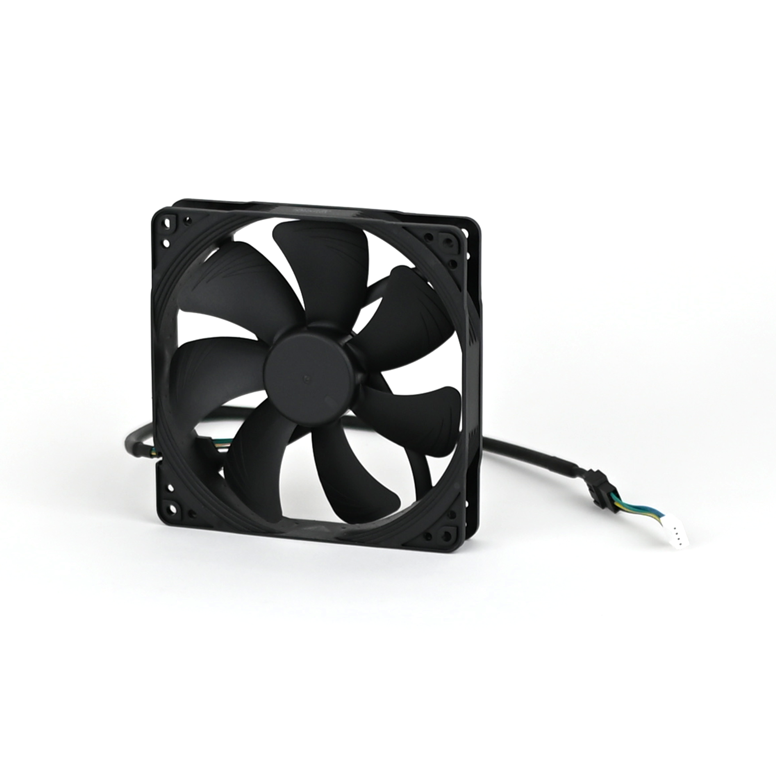
Parts

Chassis fan

Cable ties
Instructions
2. Remove the left side panel.
3. Disconnect the connector from PCB and the extension cable from the fan cable. NOTE: the extension cable can be reused for the replacement fan.
4. Cut any cable ties fastening the cable to the roaster.
5. Pull the cable through, so it is loose and hanging from the roaster.
6. Take a photo/reference of the orientation of the ventilation fan before removal. NOTE: fan is meant to draw air into the roaster to keep components cool.

The correct orientation of the fan is shown in the image on the left, seen from the inside of the roaster.
7. Orientate the roaster, so the back is facing you.
8. Using the Phillips screwdriver bit, remove the four fourscrews holding the fan in place.

NOTE: Screws have split washers on them, please take care not to lose them!
9. Remove the old ventilation fan.

10. Locate the new fan in the correct orientation.

11. Fasten all four bolts until tight.

Align holes on the fan with holes on the back of the roaster before installing bolts
12. Feed cable over the top of the chaff separator.
13. Attach extension cable to fan connector.
14. Attach the connector to PCB.
NOTE: PCB reads “VentFan1”
15. Fasten any loose cables to the roaster.
16. Install the left side panel.
18. Plug the roaster in, turn it on and test the chassis fan. If it doesn’t work, contact the ROEST support team.
How to change: Buzzer
This is the guide on how to change the buzzer on your ROEST.

Where to buy buzzer?
If you are sure your buzzer is broken (you have talked to our Support Team) visit our e-shop to purchase a new one!
Before you start
⚠️DISCLAIMER
Information in this document is believed to be accurate and reliable. However, the manufacturer does not give any representations or warranties, expressed or implied, as to the accuracy or completeness of such information and shall have no liability for the consequences of the use of such information. The manufacturer is not liable or responsible for any problems arising from the attempted repair. The manufacturer reserves the right to make changes to information published in this document, including without limitation specifications and product descriptions, at any time and without notice. The manufacturer's products are not designed, authorized, or warranted to be suitable for use in applications where failure or malfunction can reasonably be expected to result in personal injury, death, or severe property or environmental damage. The manufacturer accepts no liability for inclusion and/or use of its products in such equipment or applications and therefore such inclusion and/or use is for the customer’s own risk.
⚠️SAFETY INSTRUCTIONS
make sure the roaster is turned off
the power cord has to be unplugged
follow the steps as instructed below
Tools

Flat ended screwdriver

Cutters
Parts

Buzzer

Cable ties

M5 x 6 cap head screw
Silicone
Instructions
2. Remove the left side panel.
3. Take a photo of the cable location on the PCB and how cables are fastened to the motor bracket ((LED1) on PCB) to know where to relocate and fasten the new component.
Buzzer connector on PCB

Cables fastened to motor bracket ((LED1) on PCB)
4. Remove the buzzer connector from PCB.

5. Using the small flat-ended screwdriver, pry the faulty buzzer away from the back plate.


6. Cut the cable ties to release the buzzer. NOTE: Take care not to cut through any cables.


Only cut the amount of cable ties required to release cable.
7. Apply four silicone dots around the buzzer, approximately 10-millimeter in size.

8. Install the buzzer.

Locate the M5 x 6 screw through the front of the back plate

Locate buzzer hole into screw and press onto the back plate.
NOTE: Ensure that the orientation of the cable is the same as in the image.
9. Plug the buzzer cable back into the PCB.

10. Cable tie the buzzer back into position.

11. Use cutters to trim the excess ends from cable ties.

12. Leave silicone to dry for approx. 30 minutes before reassembling.
13. Remove the M5 x 6 cap head screw after the silicone has been left to dry for 30 minutes.

14. Install the left side panel.
16. Plug the roaster in, turn it on and test the buzzer. If it doesn’t work, contact the ROEST support team.
How to change: Power supply
This is the guide on how to change the power supply on your ROEST.

Where to buy power supply?
If you are sure your power supply is broken (you have talked to our Support Team) visit our e-shop to purchase a new one!
Before you start
⚠️DISCLAIMER
Information in this document is believed to be accurate and reliable. However, the manufacturer does not give any representations or warranties, expressed or implied, as to the accuracy or completeness of such information and shall have no liability for the consequences of the use of such information. The manufacturer is not liable or responsible for any problems arising from the attempted repair. The manufacturer reserves the right to make changes to information published in this document, including without limitation specifications and product descriptions, at any time and without notice. The manufacturer's products are not designed, authorized, or warranted to be suitable for use in applications where failure or malfunction can reasonably be expected to result in personal injury, death, or severe property or environmental damage. The manufacturer accepts no liability for inclusion and/or use of its products in such equipment or applications and therefore such inclusion and/or use is for the customer’s own risk.
⚠️SAFETY INSTRUCTIONS
make sure the roaster is turned off
the power cord has to be unplugged
follow the steps as instructed below
Tools

2.5-millimeter hexagonal key

Padded mat

Philips screwdriver
Parts


Using the Philips screwdriver loosen the hose clip

Pull off the exhaust tube

Pull off the exhaust tube
4. Take a reference picture of the location of the cables prior to removing them.

5. Remove the 5 horse-shoe cables from the power supply.

Loosen the screws with the Philips screwdriver

Cables removed
6. Place the padded mat on the desk and lay the roaster down on its side, ensuring that the mat protects the right-side panel (which remains installed).

Padded mat should be underneath
7. Using a 2.5-millimeter hexagonal key, remove the three cap head bolts on the roaster’s base.

8. Remove the power supply from the roaster.

9. Insert the new power supply and align the holes to screw the three bolts on the base.
10. Position the roaster back up.
11. Reattach the five cables into the power pack using the image taken in step 4.

12. Reattach the exhaust tube.


Ensure that you fasten the hose clip around the chaff separator
13. Install the left side panel.
15. Plug the roaster in, turn it on and test it. If it doesn’t work, contact the ROEST support team.
How to remove and install side panels

Before you start
⚠️DISCLAIMER
Information in this document is believed to be accurate and reliable. However, the manufacturer does not give any representations or warranties, expressed or implied, as to the accuracy or completeness of such information and shall have no liability for the consequences of the use of such information. The manufacturer is not liable or responsible for any problems arising from the attempted repair. The manufacturer reserves the right to make changes to information published in this document, including without limitation specifications and product descriptions, at any time and without notice. The manufacturer's products are not designed, authorized, or warranted to be suitable for use in applications where failure or malfunction can reasonably be expected to result in personal injury, death, or severe property or environmental damage. The manufacturer accepts no liability for inclusion and/or use of its products in such equipment or applications and therefore such inclusion and/or use is for the customer’s own risk.
⚠️SAFETY INSTRUCTIONS
make sure the roaster is turned off
the power cord has to be unplugged
follow the steps as instructed below
Tools

2-millimeter and 4-millimeter hexagonal tool
T20 Torx screwdriver or 3-millimeter hexagonal tool.

Padded mat
How to remove side panels
1. Place the roaster on a padded mat to provide a solid base for the machine to stand on once the side panel is removed so it is easier to work with.
3. Remove the trier and the cooling tray to work easier.
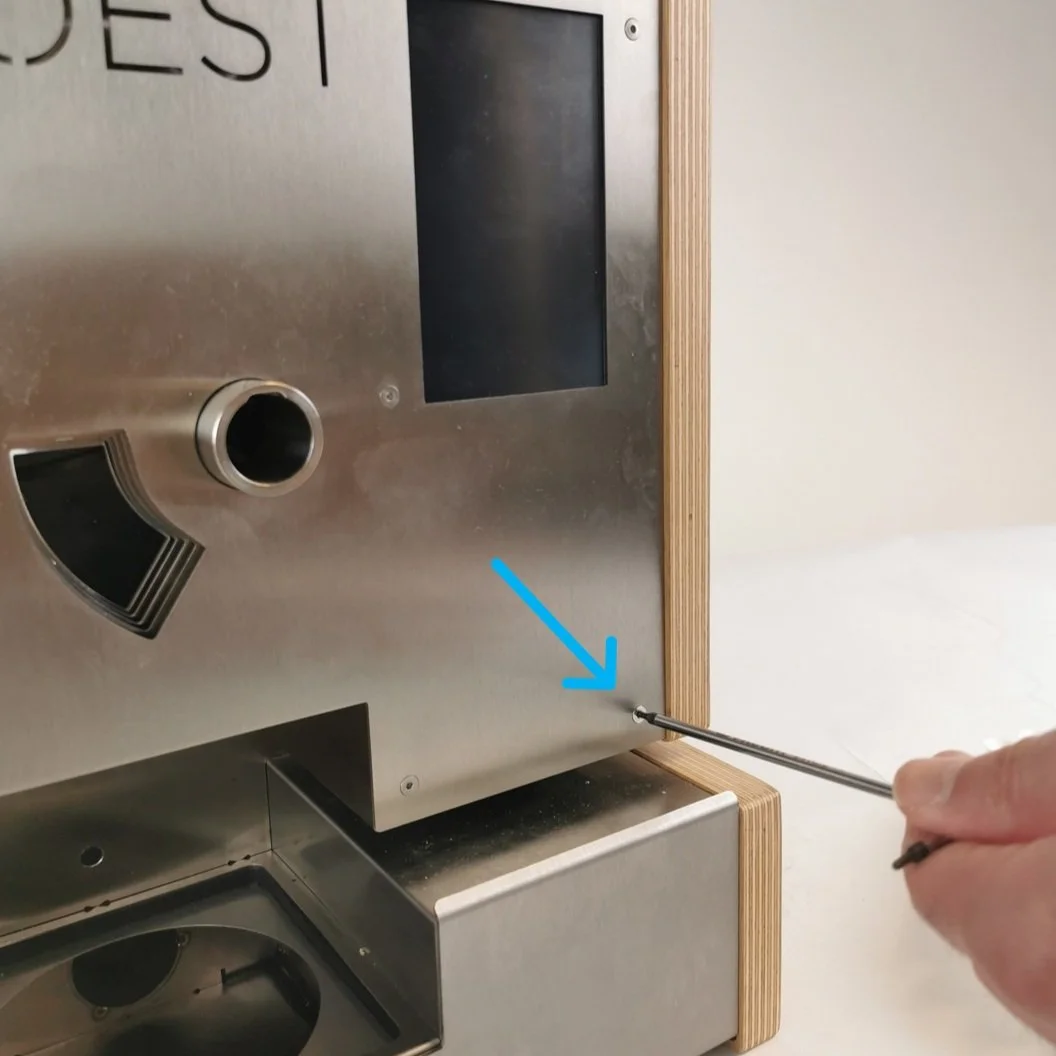
4. With the 2-millimeter hex tool, remove the countersunk bolt from the front décor plate (bottom left at the front).

For left side panel removal
For right side panel removal
5. Remove the screws at the back. Depending on the machine model, you must use a TX20 (wood) or a 3-millimeters hex tool (black). Some older models have three screws instead of four.

For left side panel removal

For right side panel removal
6. Remove the three screws under the roaster corresponding to the panel you want to take off. You can gently lay the roaster on its side or push the machine to the edge of the table so that the line of screws is visible.

Lay the roaster gently on its side.

Or push the machine to the edge of the table so that the line of screws is visible.
7. When you are taking off the side panel, loosen the cap head bolt (on the inside of the machine) holding the panel in place using the 4-millimeters hex tool.


8. Gently take the side panel off and place it on a protective surface to keep it safe.

How to install side panels
1. Start installing the side panel from the front and below. Fit the sleeve bearing in the wooden panel into the small metal projection on the side.

Metal projection

Sleeve bearing
2. Fit the brackets into the metal plates.

The side bracket of the panel goes inside the front plate

The back bracket of the panel goes below the backplate
3. When installing the left side panel, install the cap head bolts with the 4-millimeters hex tool once it is in place. Tighten it while pushing the roaster together.

Unfired bolt

You can use your body as a counterweight
4. Take the 2-millimeter hex tool and tighten the countersunk bolt on the front. Do not overtighten it.

For left side panel installation

For right side panel installation
5. Install the back screws and the bottom screws. Do not fully tighten them until the last one is in its place.

Push the machine to the edge of the table when installing the bottom screws
6. Once the last bolt is in, push the roaster together (move the side panels inwards) and tighten the screws (no need to apply a lot of torque). Make sure that no cables are being squeezed.
Video instructions
This video shows how to remove and replace the black side panels, but it can also be used for wooden side panels. The only difference is that the type of screws is different.
How to change: BT temperature sensor

Where to buy temperature sensors?
If you are sure that a temperature sensor in your roaster is broken (you have talked to our Support Team) visit our e-shop to purchase a new one!
Before you start
⚠️DISCLAIMER
Information in this document is believed to be accurate and reliable. However, the manufacturer does not give any representations or warranties, expressed or implied, as to the accuracy or completeness of such information and shall have no liability for the consequences of the use of such information. The manufacturer is not liable or responsible for any problems arising from the attempted repair. The manufacturer reserves the right to make changes to information published in this document, including without limitation specifications and product descriptions, at any time and without notice. The manufacturer's products are not designed, authorized, or warranted to be suitable for use in applications where failure or malfunction can reasonably be expected to result in personal injury, death, or severe property or environmental damage. The manufacturer accepts no liability for inclusion and/or use of its products in such equipment or applications and therefore such inclusion and/or use is for the customer’s own risk.
⚠️SAFETY INSTRUCTIONS
make sure the roaster is turned off
the power cord has to be unplugged
follow the steps as instructed below
Tools

Cutters

10-millimeter wrench
Parts

BT Sensor
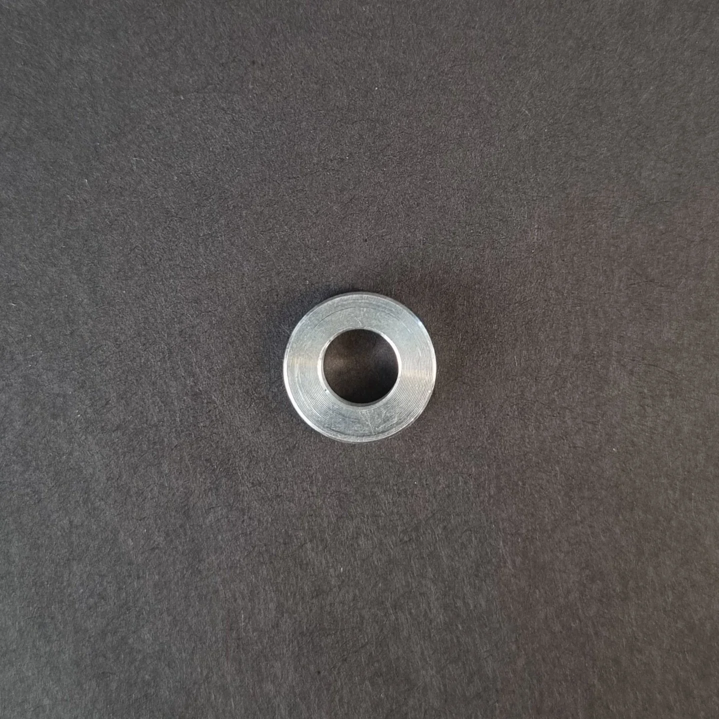
Aluminum Spacer. You will find this on the old sensor.
Cable Ties
Instructions
Follow this numbered guide below step by step.
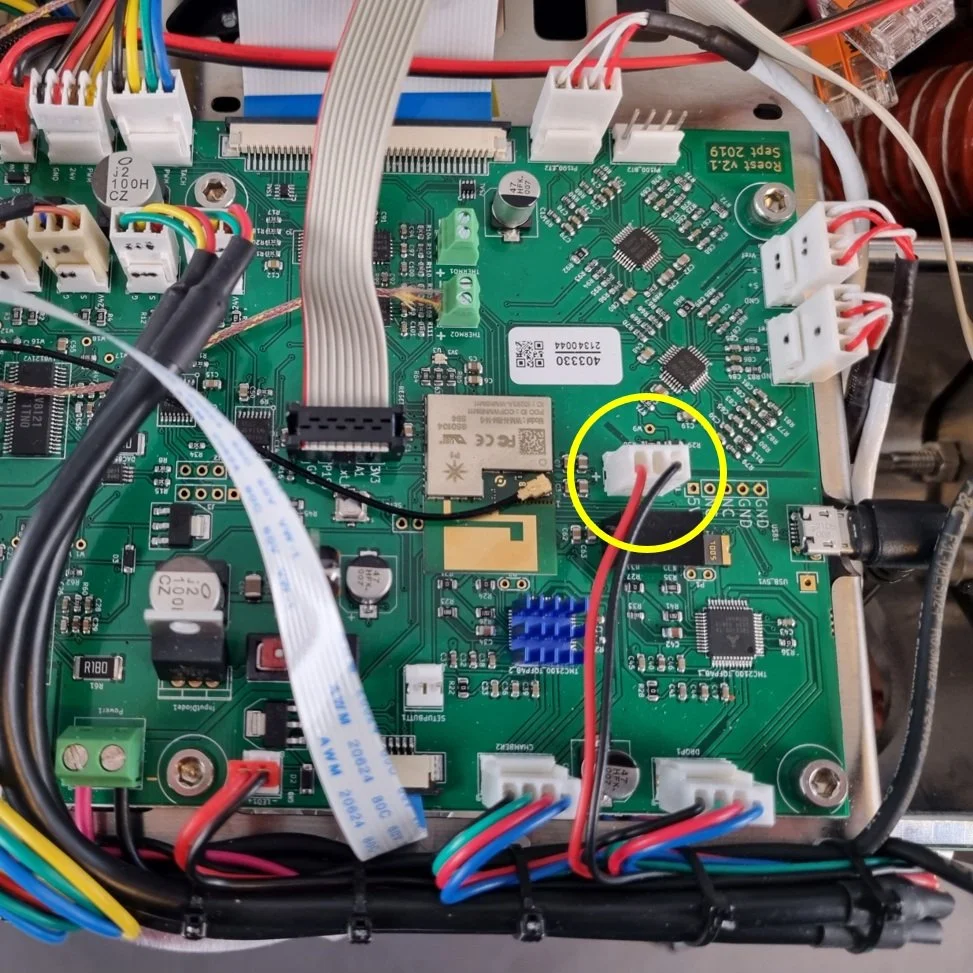
3. Take a photo/make a reference of cable locations on the PCB so you can reinstall the cables in the correct position.

4. Remove the BT cable from the PCB.

1. Unplug the BT sensor

2. Unplug the USB1 cable

3. Let the BT sensor come out and plug in the USB cable
5. Cut cable ties holding the BT sensor to the motor bracket.

6. Loosen the BT sensor with a 10-millimeter wrench and remove it from the back plate.

7. Take off the aluminum spacer from the BT sensor.
8. Place the aluminum spacer on the new BT Sensor.
9. Locate the BT sensor in its threaded hole by hand, ensuring that the aluminum spacer stays on the BT sensor and continue until finger tight.

NOTE: when rotating the BT sensor by hand, ensure that there is little resistance so as not to damage the thread.
10. Tighten with a 10-millimeter wrench. Do not overtighten, as this can strip the thread and scrap the back plate.
11. Plug BT Sensor into the original spot within the PCB.
12. Tie the remaining cable to the motor bracket in the original place
NOTE: The cable should not touch the rotating pulley. This can damage/destroy the sensor over time.

13. Install side panels.
15. Plug the roaster in, turn it on and test the BT temperature sensor. If you read NaN on the touchscreen, something is wrong. If it doesn’t work, contact the ROEST support team.
How to change: ET temperature sensor
How to change the ET temperature sensors on your ROEST.
Where to buy temperature sensors?
If you are sure that a temperature sensor in your roaster is broken (you have talked to our Support Team) visit our e-shop to purchase a new one!
Before you start
⚠️DISCLAIMER
Information in this document is believed to be accurate and reliable. However, the manufacturer does not give any representations or warranties, expressed or implied, as to the accuracy or completeness of such information and shall have no liability for the consequences of the use of such information. The manufacturer is not liable or responsible for any problems arising from the attempted repair. The manufacturer reserves the right to make changes to information published in this document, including without limitation specifications and product descriptions, at any time and without notice. The manufacturer's products are not designed, authorized, or warranted to be suitable for use in applications where failure or malfunction can reasonably be expected to result in personal injury, death, or severe property or environmental damage. The manufacturer accepts no liability for inclusion and/or use of its products in such equipment or applications and therefore such inclusion and/or use is for the customer’s own risk.
⚠️SAFETY INSTRUCTIONS
make sure the roaster is turned off
the power cord has to be unplugged
follow the steps as instructed below
Tools
6-millimeter, 10-millimeter and 12-millimeter wrench

3-millimeter hexagonal key
Cutters

3-millimeter hexagonal tool bit

Small ratchet
Parts
ET sensor
Cable ties
Tray, or similar, to keep removed components
Instructions
Follow this numbered guide below step by step.
3. If your roaster has First Crack detection, remove it by pulling it gently and disconnecting the cable from the PCB.

4. Using the 12-millimeter wrench, remove the proximity sensors from the drop door. These can be left cabled into the roaster but moved out of the way for easy access.

5. Remove the charge handle.

6. Remove the exhaust pipe from the bean stopper exhaust (top) and chaff separator (bottom).


7. Using a 6-millimeter wrench, remove three off black First Crack “grommets”.


8. Remove the M4 x 6 Cap head screw holding the bean-stopper using the small ratchet with a 3-millimeter hexagonal tool bit.


9. Using a 3-millimeter hexagonal key, loosen and remove four off M4 x 6 cap head screws retaining the bean-stopper in position.

10. Once the screws from steps 8 and 9 have been removed, tilt the exhaust duct from the bean stopper upwards and pull the bean stopper out.


This will give you a clear view inside the roasting drum to install the new ET sensor.

11. Unplug the ET sensor from the PCB.

12. Cut cable ties holding the cable in place (two). Use the cutters.


13. Use a 10-millimeter spanner/wrench to loosen the M6 hexagonal nut holding the ET sensor in place.

14. Remove the ET sensor.
15. Take the new ET sensor and screw the M6 hexagonal nut onto the thread. The sensor should have a blacked-out area to indicate the length at which the sensor should be positioned in the drum.

16. Screw the ET sensor into the back plate. NOTE: Please ensure no resistance when rotating so as not to damage the thread in the back plate.

17. Before fastening, the orientation of the sensor is critical for it to work. From the front of the roaster, the orientation of the sensor must be as follows: The blue stripe should be on the right, and the white stripe in the middle should be completely vertical. If this criterion is met, fasten with the 10-millimeter wrench.
18. When fastening the sensor, ensure that nothing of the black area is visible inside the drum; if it is, you have screwed the sensor too far in.
19. If the criterion from steps 17 and 18 have been met, the nut can be tightened. Do not move forward until the orientation and length of the sensor have been set correctly.
20. Plug the ET sensor into the original spot on the PCB.

21. Tie two new cable ties to the motor bracket where you removed the cable ties earlier.


NOTE: Cable should not touch rotating pulley. This can damage/destroy the sensor over time.
22. Use cutters to trim excess ends on cable ties.

23. Continue to reassemble.

1. Push exhaust duct to original position

2. Tighten screws retaining bean-stopper

3. Install screw holding bean-stopper

4. Tighten FC grommets

5. Install exhaust pipe

6. Install charge handle

7. Screw the drop door sensors
8. Install FC card

9. Plug FC cable into PCB
10. First Crack card should NOT touch the back plate of the roaster.
24. Install side panels.
26. Plug the roaster in, turn it on and test the ET temperature sensor. Something is wrong if you see NaN on the touchscreen instead of a temperature where you normally read the ET temperature. Please contact the ROEST support team.
How to change: Drum window LED light
How to change the LED light of the drum window on your ROEST.

Where to buy drum window LED light?
If you are sure the LED light of the drum window is broken (you have talked to our Support Team) visit our e-shop to purchase a new one!
Before you start
⚠️DISCLAIMER
Information in this document is believed to be accurate and reliable. However, the manufacturer does not give any representations or warranties, expressed or implied, as to the accuracy or completeness of such information and shall have no liability for the consequences of the use of such information. The manufacturer is not liable or responsible for any problems arising from the attempted repair. The manufacturer reserves the right to make changes to information published in this document, including without limitation specifications and product descriptions, at any time and without notice. The manufacturer's products are not designed, authorized, or warranted to be suitable for use in applications where failure or malfunction can reasonably be expected to result in personal injury, death, or severe property or environmental damage. The manufacturer accepts no liability for inclusion and/or use of its products in such equipment or applications and therefore such inclusion and/or use is for the customer’s own risk.
⚠️SAFETY INSTRUCTIONS
make sure the roaster is turned off
the power cord has to be unplugged
follow the steps as instructed below
Tools

10-millimeter spanner/wrench/socket

2-millimeter hexagonal key

Cutters

Bean sample tray or similar, to prop the roaster at an angle for easy of disassembling
Parts

Plate 3 with LED light attached

Cable ties
Instructions
Step-by-step guide:
2. Remove the front décor plate.
3. Orientate the roaster so that the front is facing you. Lift the front of the roaster and place an item underneath to tilt the roaster back (for this example we have used a few sample trays).

This is to give adequate access to the window LED and to enable the removal of aluminum spacers easier.
4. Remove the LED cable from the PCB and cut any cable ties securing it to the motor bracket.


5. Remove the protective sleeve and keep it for reinstallation. NOTE: if the protective sleeve is damaged, e.g., if a cable can be seen through the sleeve, discard it.

6. Pull the LED cable through the hole located in plate 1.


7. Remove the 6-millimeter nuts. Use the 10-millimeter wrench to loosen them and unscrew them by hand.


8. Remove plate 4 and the four aluminum spacers behind it.

1. Plate 4 removal
2. Take off the spacers
9. Remove plate 3 with the old LED light.

Plate 3 removal

This plate can be scrapped. Separate the metal part from the electronic part, and dispose of it responsibly.
NOTE: Check if the aluminum spacer is stuck to the backside of “Plate 3”; remove the spacer if it has adhered to the aluminum tape.
10. Install the new plate 3 with LED.
1. Ensure that the four aluminum spacers are on top of plate 2.

2. Install the new plate 3 and leave the cable loose.
11. Install the four aluminum spacers on top of Plate 3.
12. Install plate 4.
Install the four nuts and tighten them with the 10-millimeter wrench. NOTE: do not over-tighten the nuts, as this could damage the threads and the subsequent plates.

13. Feed the LED cable through the hole in plate 1 (this plate is the widest of the four plates).

14. Feed the protective sleeve over the end of the LED cable where it should touch the backside of plate 1.


15. Cable tie the protective sleeve and LED cable to plate 1.

Cable tie the sleeve at the top of plate one.
16. Plug the LED cable back into the original location on the PCB. NOTE: the PCB location reads “LED2”.

17. Tie loose cables to the motor bracket.

18. Install front décor plate.
20. Plug the roaster in, turn it on and test the drum window LED light. If it doesn’t work, contact the ROEST support team.
Video instructions
How to remove and install front décor plate

Before you start
⚠️DISCLAIMER
Information in this document is believed to be accurate and reliable. However, the manufacturer does not give any representations or warranties, expressed or implied, as to the accuracy or completeness of such information and shall have no liability for the consequences of the use of such information. The manufacturer is not liable or responsible for any problems arising from the attempted repair. The manufacturer reserves the right to make changes to information published in this document, including without limitation specifications and product descriptions, at any time and without notice. The manufacturer's products are not designed, authorized, or warranted to be suitable for use in applications where failure or malfunction can reasonably be expected to result in personal injury, death, or severe property or environmental damage. The manufacturer accepts no liability for inclusion and/or use of its products in such equipment or applications and therefore such inclusion and/or use is for the customer’s own risk.
⚠️SAFETY INSTRUCTIONS
make sure the roaster is turned off
the power cord has to be unplugged
follow the steps as instructed below
Tools

2 and 3-millimeter hexagonal tool
How to remove front décor plate
1a. Pull out the trier and the drop handle.
The black drop handle is attached by a set screw. Use the 3-millimeter hexagonal tool to remove it.


For the wooden drop handle, just pull it to take it off.
2. Disconnect the touchscreen cable from PCB. Push back the black retaining clip and detach the cable. Ensure the retaining clip is left in place at the connection point.


3. Remove the three front plate screws by using the 2-millimeter hexagonal tool.

4. Slowly remove the front décor plate from the roaster. Take off the front décor plate and place it on a protective surface. Leave the 40-pin cable connected to the screen.


How to install front décor plate
1. Feed the touchscreen cable through the original slots on the roaster and put the front décor plate in its position.

1. Cable through the frontal slot

2. Front décor plate installation

3. Cable through the top slot
2. Install the touchscreen cable into the PCB. Push the black retaining clip and insert the cable (you must twist it to show the blue band of the cable facing up).

You can use a flat head screwdriver to keep the clip “open” while inserting the cable.

Once in position, fasten it by pushing the clip back to its original position.
3. Install three M3 x 6 countersunk screws into the front décor plate by using the 2-millimeter hexagonal key.

4. Install the drop handle and the trier. For a wooden handle, push it through. For a black drop handle install the set screw using the 2-millimeter hexagonal tool.

How to change: Bean cooler LED light
How to replace a touch screen on your ROEST.

Where to buy LED light?
If you are sure your LED-light is broken (you have talked to our Support Team) visit our e-shop to purchase a new one!
Before you start
⚠️DISCLAIMER
Information in this document is believed to be accurate and reliable. However, the manufacturer does not give any representations or warranties, expressed or implied, as to the accuracy or completeness of such information and shall have no liability for the consequences of the use of such information. The manufacturer is not liable or responsible for any problems arising from the attempted repair. The manufacturer reserves the right to make changes to information published in this document, including without limitation specifications and product descriptions, at any time and without notice. The manufacturer's products are not designed, authorized, or warranted to be suitable for use in applications where failure or malfunction can reasonably be expected to result in personal injury, death, or severe property or environmental damage. The manufacturer accepts no liability for inclusion and/or use of its products in such equipment or applications and therefore such inclusion and/or use is for the customer’s own risk.
⚠️SAFETY INSTRUCTIONS
make sure the roaster is turned off
the power cord has to be unplugged
follow the steps as instructed below
Tools

Cutters
Parts

Bean cooler LED assembly

Cable ties to re-cable the LED light to the motor bracket.
Instructions
Step-by-step guide:
1. Remove the top plate. You can read how to do it here.
2. Remove the left side panel. Click here to see how to do it.
3. To know where to relocate and fasten the new LED light, you can take a photo of the cable location on the PCB (connector named LED1 on the PCB) and how cables are fastened to the motor bracket.

From top

From side
4. Disconnect bean cooler LED light cable from PCB.

5. Remove the old Bean Cooler LED Assembly. NOTE: if the LED is damaged, disassemble it from the bracket and dispose of it responsibly.


6. Cut cable ties to release LED cable by using the cutters.
CAUTION! take care not to cut through any cables. NOTE: Only cut the number of cable ties required to release that cable.


7. Slide the new bean cooler LED into position. NOTE: if the component does not locate by hand, gently tap the component into place until seated.


8. Plug the cable back into the PCB slot (connector named LED1).

9. Start tying the LED cable into position. Tie the LED cable into the remaining cables along the motor bracket.

Ensure that the cable has been fastened in position with a loop. This is in case the PCB needs to be changed.

IMPORTANT: Ensure that proximity extension cables are not cable tied.
10. Trim the excess from cable ties by using the cutters.
11. Before putting the left side panel and top plate back on the roaster, ensure that there is no excess cable from Bean Cooler LED Assembly that can be squeezed and damaged. IMPORTANT: If there is excess cable when the left side panel is fastened in place, this can cause the cable to become damaged and cause electrical faults in the roaster.

LED cable should look like this (no excess)
12. Install the left side panel.
13. Install the top plate.
14. Plug the roaster in, turn it on and test the LED light. If it doesn’t work, contact the ROEST support team.
How to change: PCB encoder
This is the guide on how to change the PCB encoder on your ROEST.

Where to buy PCB encoder?
If you are sure your encoder is broken (you have talked to our Support Team) visit our e-shop to purchase a new one!
Before you start
⚠️DISCLAIMER
Information in this document is believed to be accurate and reliable. However, the manufacturer does not give any representations or warranties, expressed or implied, as to the accuracy or completeness of such information and shall have no liability for the consequences of the use of such information. The manufacturer is not liable or responsible for any problems arising from the attempted repair. The manufacturer reserves the right to make changes to information published in this document, including without limitation specifications and product descriptions, at any time and without notice. The manufacturer's products are not designed, authorized, or warranted to be suitable for use in applications where failure or malfunction can reasonably be expected to result in personal injury, death, or severe property or environmental damage. The manufacturer accepts no liability for inclusion and/or use of its products in such equipment or applications and therefore such inclusion and/or use is for the customer’s own risk.
⚠️SAFETY INSTRUCTIONS
make sure the roaster is turned off
the power cord has to be unplugged
follow the steps as instructed below
Tools

2-millimeter hexagonal key

10-millimeter spanner/wrench/socket
Parts

Encoder PCB
Instructions
Step-by-step guide:
1. Remove the top plate and cable. You can read how to do it here.
2. Place the top plate on a protective surface and loosen the “grub screw” on the encoder knob. Use the 2-millimeter hexagonal key.
3. Remove the encoder knob and nylon washer.


4. Use the 10-millimeter spanner/wrench/socket to loosen the retaining nut and remove it. Take off the old encoder PCB and screw the nut back onto the threaded portion.
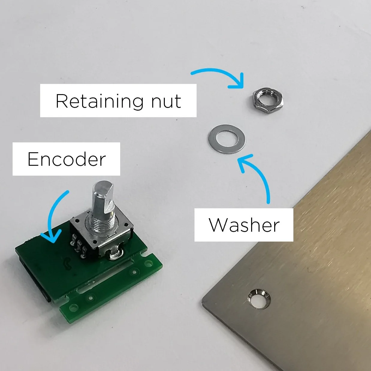
5. Take the new encoder PCB, and remove the retaining nut and the washer.
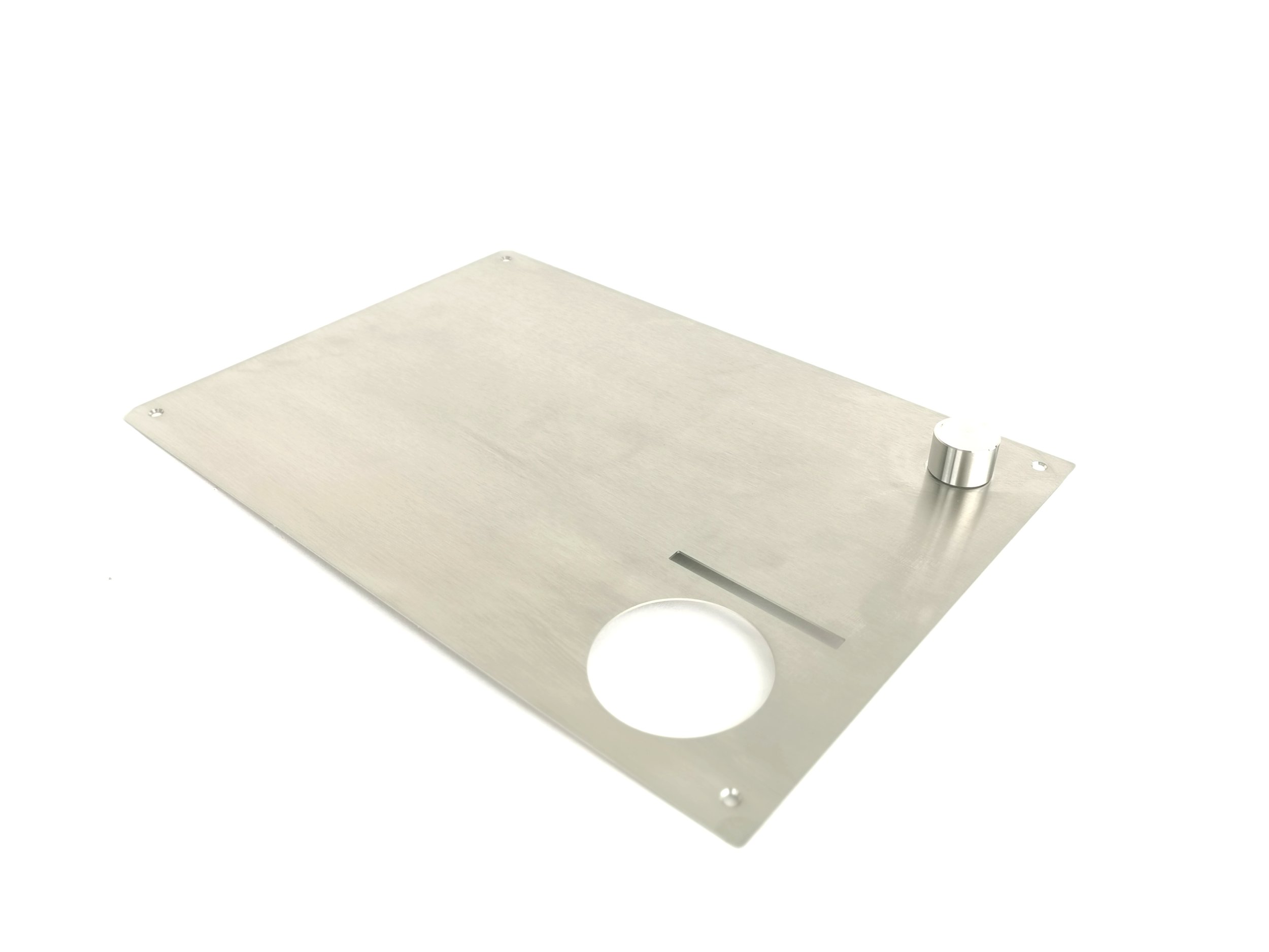
6. Locate the D-Shaped encoder PCB portion through the top plate hole.


7. Locate the washer and retaining nut on the threaded part (on the other side of the top plate).

First, fasten it by hand, and tighten it using the 10-millimeter wrench.

The orientation of the encoder must be as original. If not, the top plate will not fit. See D-shaped portion orientation.
8. Place the encoder knob (including the nylon washer) on top of the D-Shaped portion.

Align the grub screw hole with the flat portion of D Shape.

9. Tighten it by using the 2-millimeter hexagonal key.

10. Install the top plate and the encoder cable.
11. Plug the roaster in, turn it on and test the encoder. If it doesn’t work, contact the ROEST support team.
How to remove and install top plate
Before you start
⚠️DISCLAIMER
Information in this document is believed to be accurate and reliable. However, the manufacturer does not give any representations or warranties, expressed or implied, as to the accuracy or completeness of such information and shall have no liability for the consequences of the use of such information. The manufacturer is not liable or responsible for any problems arising from the attempted repair. The manufacturer reserves the right to make changes to information published in this document, including without limitation specifications and product descriptions, at any time and without notice. The manufacturer's products are not designed, authorized, or warranted to be suitable for use in applications where failure or malfunction can reasonably be expected to result in personal injury, death, or severe property or environmental damage. The manufacturer accepts no liability for inclusion and/or use of its products in such equipment or applications and therefore such inclusion and/or use is for the customer’s own risk.
⚠️SAFETY INSTRUCTIONS
make sure the roaster is turned off
the power cord has to be unplugged
follow the steps as instructed below
Tools

2-millimeter hexagonal tool
How to remove the top plate
Take off the hopper and follow the instruction below.
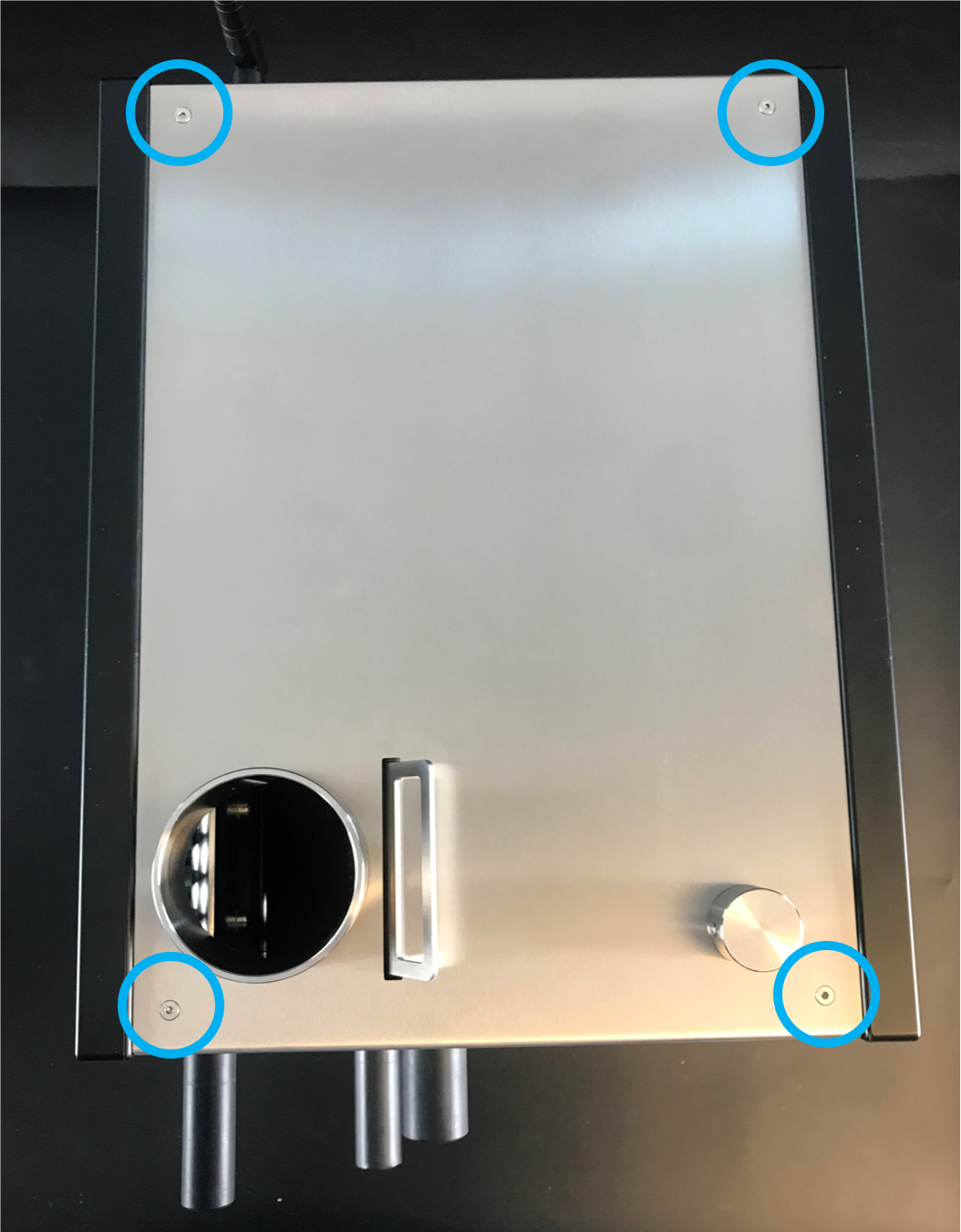
1. There are four screws on the top

2. Use the 2-millimeter hexagonal tool to remove them

3. Take off the plate slowly
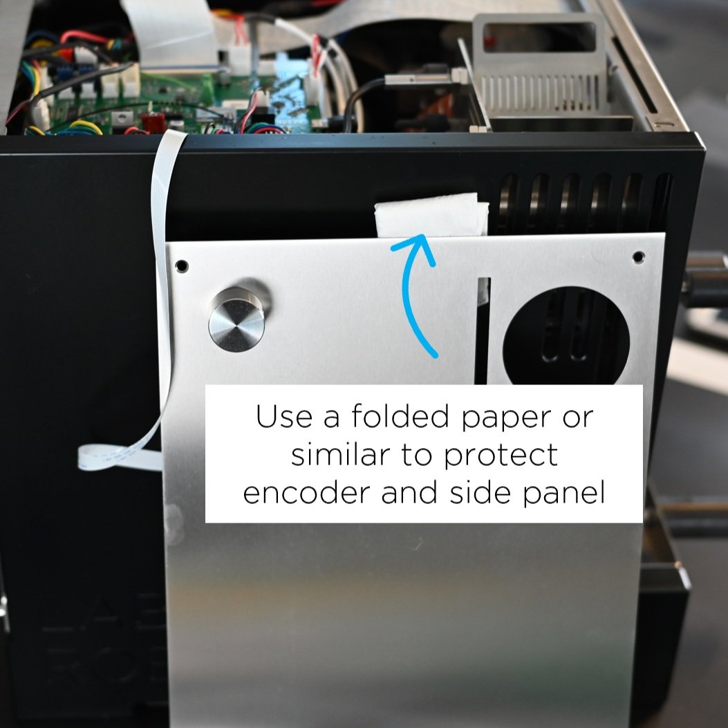
5. Gently, lean the plate on the side of the roaster.
If you need to remove the cable attached to the encoder, push the black retaining clip and disconnect the cable.

The following video shows you how to remove the top plate.
How to install the top plate
If the encoder cable has been detached, you must connect it before you install the top plate. Push the black retaining clip and insert the cable through the slot.

Make sure the blue band on the cable is facing up.

Ensure the cable is inserted into the slot and the black retaining clip is fully fastened.
Now, install the top plate.

Follow this order to tighten the screws

Make sure to press front plate when installing screw 1 and 3
The following video shows you how to install the top plate.
How to change: S/L100 PCB
How to replace the PCB on your ROEST S100 or ROEST L100.

Where to buy a new PCB?
If you are sure your PCB is not working well (you have talked to our Support Team), visit our e-shop to purchase a new one!
Before you start
⚠️DISCLAIMER
Information in this document is believed to be accurate and reliable. However, the manufacturer does not give any representations or warranties, expressed or implied, as to the accuracy or completeness of such information and shall have no liability for the consequences of the use of such information. The manufacturer is not liable or responsible for any problems arising from the attempted repair. The manufacturer reserves the right to make changes to information published in this document, including without limitation specifications and product descriptions, at any time and without notice. The manufacturer's products are not designed, authorized, or warranted to be suitable for use in applications where failure or malfunction can reasonably be expected to result in personal injury, death, or severe property or environmental damage. The manufacturer accepts no liability for inclusion and/or use of its products in such equipment or applications and therefore such inclusion and/or use is for the customer’s own risk.
⚠️SAFETY INSTRUCTIONS
make sure the roaster is turned off
the power cord has to be unplugged
follow the steps as instructed below
Tools
2-millimeter and 3-millimeter hexagonal tool
Parts

S100 or L100 PCB. On an L100 PCB, these two black chips must be present.
Instructions
Preparations:
Turn on the machine, go into the First Crack Settings menu and take a note of the settings. They will reset to factory settings and need to be readjusted after the replacement.
Install the encoder flex cable to the PCB in before placing it into the machine
Step-by-step guide:
1. Remove the top plate (remove the hopper before you start).
2. Take a photo or make a reference to the current location of the connections on the PCB. You can use tape or a marker (see the example below).


3. Disconnect all of the cables on the PCB. IMPORTANT! There is no need to cut any cable ties harnessing the cables to the motor bracket. You will detach the cables by pulling them back gently. Use a screwdriver for the following connectors:

Unscrew the bolts

L100: Unscrew the bolts

You can help yourself with a screwdriver to detach this little cable
For the two cables attached by a black retaining clip, push it back and detach the cable. Ensure the retaining clip is left in place at the connection point.


4. Unscrew four off M4 x 6 cap head bolts from the motor bracket. Use the 3-millimeter hexagonal tool.

5. Lift off the PCB slowly. CAUTION! Nylon washers located underneath the PCB could drop inside the machine if not handled carefully. Ensure that the four washers are placed over the threaded holes after this operation.

6. Remove the new PCB from the bag & place the old PCB in the bag.
7. Place the new PCB in the original position on the motor bracket. CAUTION! Operate gently to ensure the nylon washers do not fall into the roaster.
8. Secure with four off M4 x 6 cap head bolts.
9. Reconnect cables as per the image/reference taken.
IMPORTANT! To make L100 sensors work, the following connections are crucial:
- Drum and inlet temperature cables must be connected correctly to work.
Yellow cable = POSITIVE
Red cable = NEGATIVE


-Extra proximity sensor cable must be connected to the 4th proximity sensor slot on PCB reading “Sensor0”.

11. Plug the roaster in, turn it on and test if the PCB has been connected correctly. For L100; if the roaster shows “0” for the drum temperature on the touchscreen, then re-check if the drum temperature cables (step 9) are correctly installed and properly inserted.
12. Once the PCB is correctly installed, please contact the ROEST support team to let us know, so that we can change over to he new PCB in our system.
13. Once your machine is switched over to the new PCB, if you have any problems connecting to the Roest server then please reset the metadata on your roaster. Enter the service menu, tap on ‘Settings’, and then tap ‘Clear Metadata’.
If the roaster doesn’t work properly after following the above steps, contact the ROEST support team for help.
How to install: First Crack Detection
This is the guide on how to install the First Crack Detector on your ROEST.
Important note: Only models starting P11_ and higher can upgrade to the First Crack Detection system.

Where to buy First Crack Detection?
If you would like to install a First Crack Detection system on your roaster visit our e-shop to buy it!
Before you start
⚠️DISCLAIMER
Information in this document is believed to be accurate and reliable. However, the manufacturer does not give any representations or warranties, expressed or implied, as to the accuracy or completeness of such information and shall have no liability for the consequences of the use of such information. The manufacturer is not liable or responsible for any problems arising from the attempted repair. The manufacturer reserves the right to make changes to information published in this document, including without limitation specifications and product descriptions, at any time and without notice. The manufacturer's products are not designed, authorized, or warranted to be suitable for use in applications where failure or malfunction can reasonably be expected to result in personal injury, death, or severe property or environmental damage. The manufacturer accepts no liability for inclusion and/or use of its products in such equipment or applications and therefore such inclusion and/or use is for the customer’s own risk.
⚠️SAFETY INSTRUCTIONS
make sure the roaster is turned off
the power cord has to be unplugged
follow the steps as instructed below
Tools

3-millimeter hexagonal key

6-millimeter spanner/wrench
Parts

First Crack card

Three rubber First Crack card holders

Cable
Instructions
Follow this numbered guide below step by step.
Remove the top plate. You can read how to do it here.
Remove the blanking bolt by using the 3-millimeter hexagonal key.
Removing the blanking bolt is essential so the First Crack card works. If the bolt is not present, continue to step 3.

3. Install the three rubber First Crack holders. Tighten them with the 6-millimeter spanner. NOTE: if already present, continue to step 4.


4. Plug the cable into the back of the First Crack card.
5. Install the First Crack card with the cable attached. The card has been designed so it can only be installed one way.

Locate it through the rubber holders.

Hold the card and pull the rubber until the card “snaps” onto the rubber holders.
6. Check the distance of the installed First Crack.

The First Crack card should NOT touch the back plate of the roaster.
7. Install the cable into the PCB – the red strip of the cable coming out from the First Crack card should face the right-side panel (as you look at the roaster from the front). That same red line should face the back of the roaster when connected to the PCB.

Push the connector to attach the cable to the PCB

This is how it should look after installation
9. Turn on the roaster.
10. Turn on First Crack detection, by following these four quick steps here.
Now you can set the BT threshold and Trigger count parameters to your liking.
You can learn more about First Crack by reading this article.
IMPORTANT! The First Crack detection system will not operate if the card is installed incorrectly. If it doesn’t work, contact the ROEST support team.
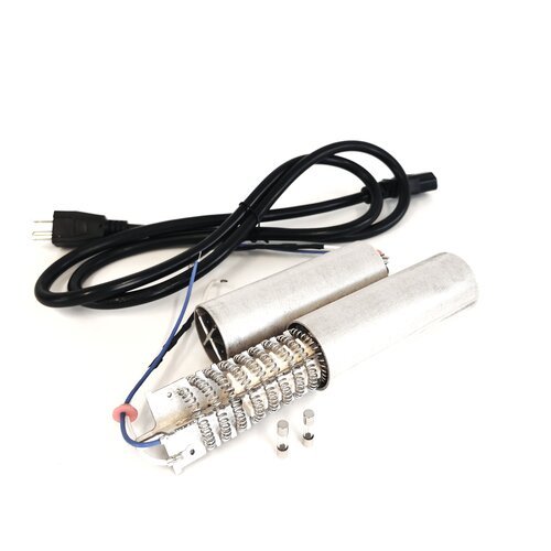
How to change: Heater fan
How to change the heater fan on your ROEST.
Where to buy heater fan?
If you are sure your heater fan is broken (you have talked to our Support Team) visit our e-shop to purchase a new one!
Before you start
⚠️DISCLAIMER
Information in this document is believed to be accurate and reliable. However, the manufacturer does not give any representations or warranties, expressed or implied, as to the accuracy or completeness of such information and shall have no liability for the consequences of the use of such information. The manufacturer is not liable or responsible for any problems arising from the attempted repair. The manufacturer reserves the right to make changes to information published in this document, including without limitation specifications and product descriptions, at any time and without notice. The manufacturer's products are not designed, authorized, or warranted to be suitable for use in applications where failure or malfunction can reasonably be expected to result in personal injury, death, or severe property or environmental damage. The manufacturer accepts no liability for inclusion and/or use of its products in such equipment or applications and therefore such inclusion and/or use is for the customer’s own risk.
⚠️SAFETY INSTRUCTIONS
make sure the roaster is turned off
the power cord has to be unplugged
follow the steps as instructed below
Tools
2.5-millimeter hexagonal key (L or T-shaped)
3-millimeter hexagonal key (T-shaped, long)
Stanley knife
Plastic gloves
Parts


NOTE: PCB reads “HeatFan2”
Disconnect the drum and inlet temperature sensor. This procedure is the same for both sensors.

Note how the wires are inserted into the screw terminal, the yellow wire is positive, and the red wire is negative.
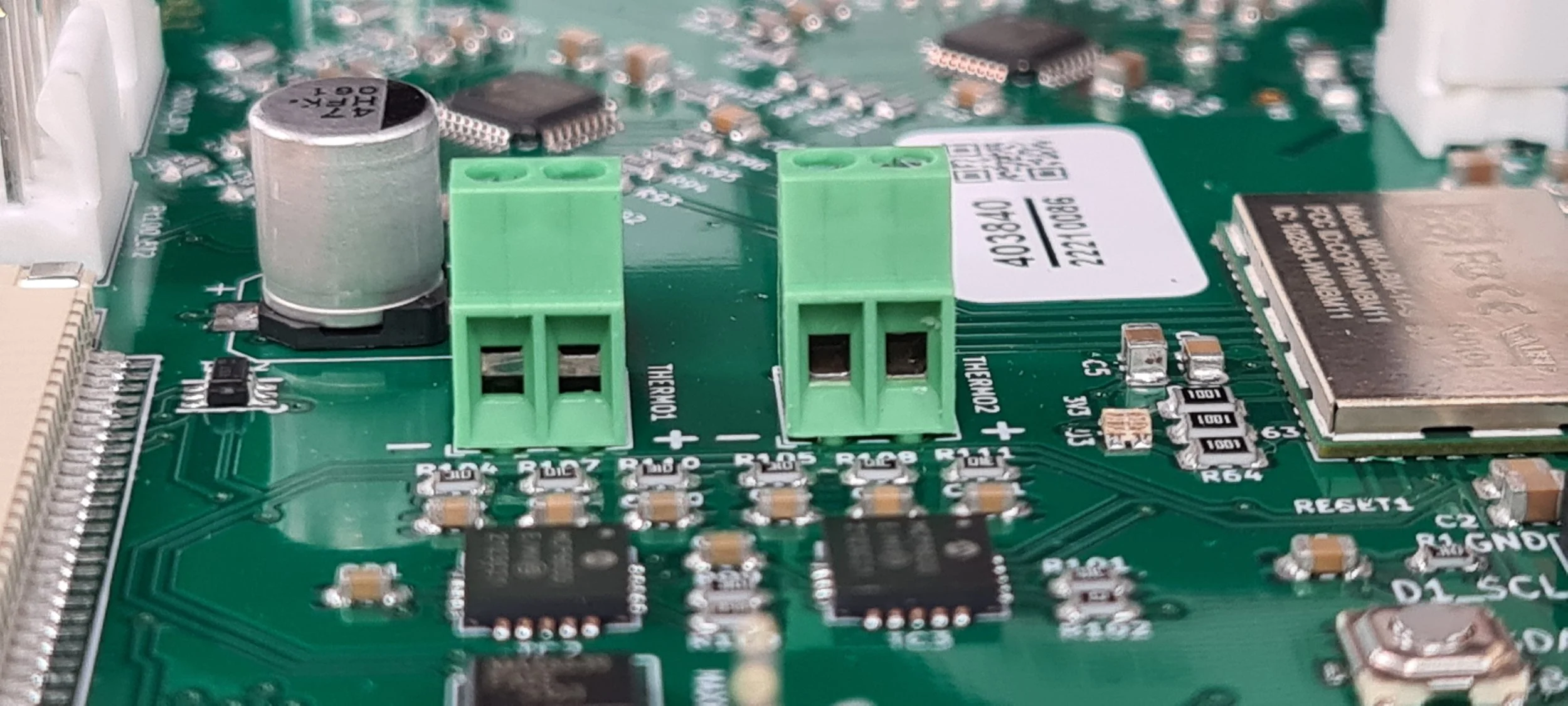
Make sure you open the hole up, as done on the right terminal. The left terminal is in the incorrect position.

Pull the cable through the holes in the heater fan.

Remove the cable completely from the heater fan.
5. Disconnect heating element cables from wago connectors and cut the cable ties. NOTE: Before disconnecting, take a photo or make a reference to ensure that the correct cable goes into the correct wago connector when reconnecting.

Cut the cable ties holding the cables from the heater fan in place. If you have extra, note how the cables are tied, so you can tie them up again when finished.
Only open the two flaps that read Wago 221.
6. Remove the heating system.
Undo the two bolts for the heating element.

Remove the heating element.

Undo one bolt loosely (don’t remove) on the inside of the heating element housing.

Undo two bolts loosely on the outside of the heating element housing, but don’t remove them. You can remove the orange hose to see better.

If you look inside the housing, it should look like this.

Pull the housing backward, so it slides away from the bolts holding it.

Pull the heating element housing with the heater fan upwards.

What it should look like after you pulled the housing off.
7. Install the new heater fan onto the old heating element housing.

The heating system you removed from the roaster should look like this.

Undo these two screws using a 2.5-millimeter hexagonal key. Hold a finger or on the back to keep the screw from spinning.

Use a spanner to hold the nut in place.

Use the spanner on the nut while undoing the screw from the other side.
Save your screws and nuts from the old heater fan; you will need them for the new one.

Cut the silicone on all sides where the fan and housing meet.

Pull the fan and housing apart.

Your old heater fan should be separated from the heating element housing at this point.

Find your new heater fan.

The orientation of the heater fan in relation to the heating element housing should be as shown in the photo above. There is a slot in the heater fan where the housing can be inserted.

Slide the housing inside the heater fan.

Insert the screws you removed from the old fan.

Turn your fan around (watch the screws so they don’t fall out).

Place the washers.

Place the nuts.

Find your spanner again to tighten the nuts.

Tighten the screws.

You need to use both your spanner and hexagonal key simultaneously.

You will need some silicone. We should provide it if you purchased a heater fan in our webshop.

You will need plastic gloves as well. Cut a hole at the tip of the bag to make a piping bag.

Use the piping bag to add silicone where the heater fan meets the heating element housing.

Add silicone to all sides.


Smear it out with your finger, removing excess silicone.


Make sure the area around the heating element stays clean.
8. Wait 24 hours for the silicone to dry.
9. Install the new heater fan system onto the roaster.

Slide the heating system onto the inlet housing.

Then push the heating system into place.

When your system has slid into place, it will look like this inside. If your mica tube is in the way, you can remove it.

Tighten the bolt inside and the two bolts on the outside. Install the mica tube if you removed it.
10. Install the heating element and connect it to the correct wago connectors (look at the image at the beginning of the guide for reference). Use a 2.5-millimeter hexagonal key to tighten the bolts.


Note the orientation of the heating element. The red rubber component should be closer to the PCB.
11. Install the drum and inlet temperature sensors if you have them:

Pull the cable through the bottom hole.

And then pull it through the top hole again.

Pull it through all the way, but not too tightly.

Make a note of the colors of the wires: Yellow is positive, and red is negative.

Make a note of the orientation on the terminal. Ensure the yellow wire goes into the positive terminal and the red wire goes into the negative terminal.
Ensure the cable is not in the way or hanging too loosely in the machine.
Do the same for the inlet temperature; insert it into the left screw terminal instead.
12. Connect the heater fan to the PCB (refer to the beginning of this guide if you are unsure of where).
13. Install back the front décor plate. Instructions here.
14. Install back the side panels. Find instructions here.
15. Install back the top plate following this guide.
16. Plug the roaster in, turn it on and test the heater fan. If it doesn’t work, contact the ROEST support team.
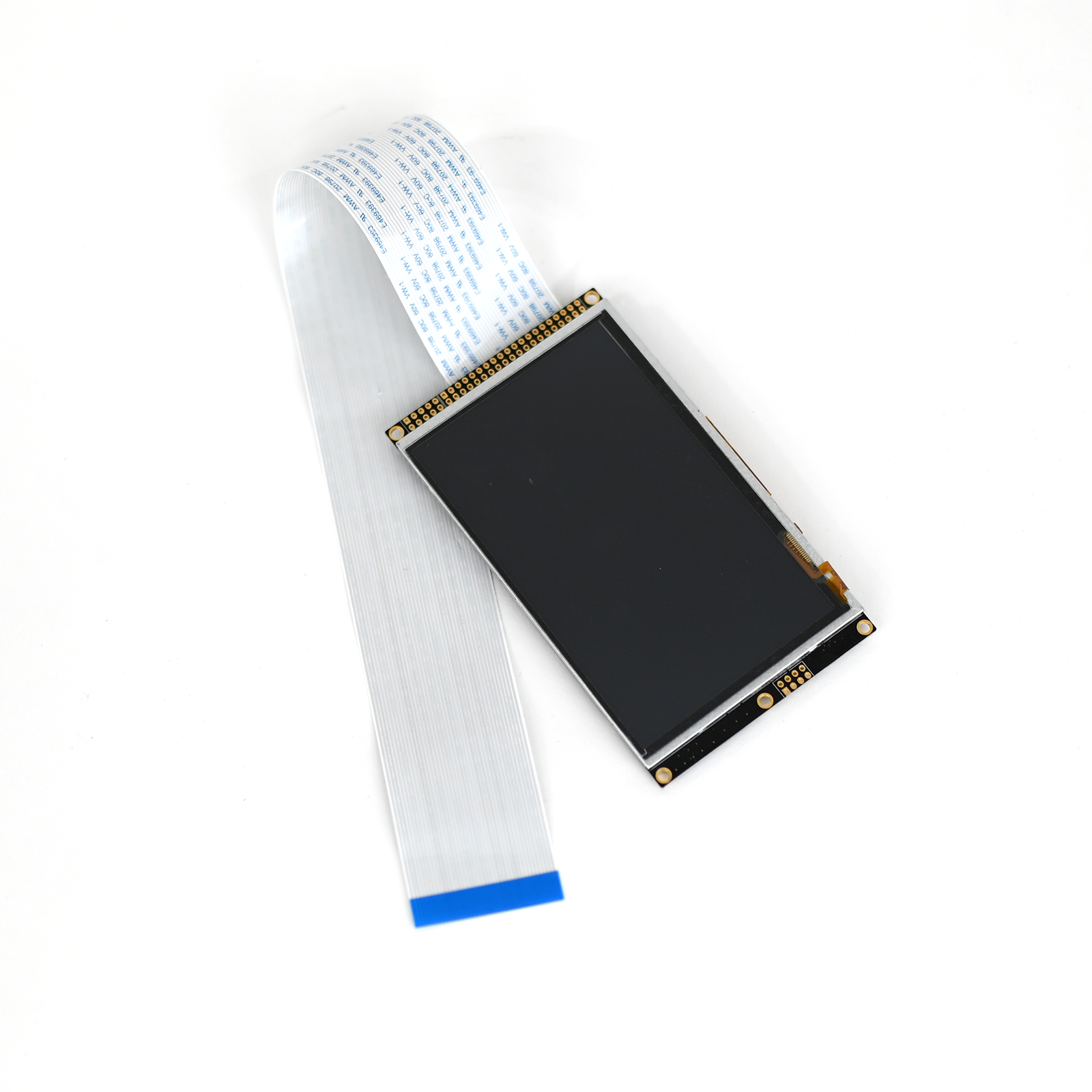
How to change: Touch Screen
How to replace a touch screen on your ROEST.
Where to buy touch screen?
If you are sure your touch screen is broken (you have talked to our Support Team) visit our e-shop to purchase a new one!
Note: sometimes touchscreen appears broken when there might be an issue with your firmware. Make sure to discuss your problem with our team.
Before you start
⚠️DISCLAIMER
Information in this document is believed to be accurate and reliable. However, the manufacturer does not give any representations or warranties, expressed or implied, as to the accuracy or completeness of such information and shall have no liability for the consequences of the use of such information. The manufacturer is not liable or responsible for any problems arising from the attempted repair. The manufacturer reserves the right to make changes to information published in this document, including without limitation specifications and product descriptions, at any time and without notice. The manufacturer's products are not designed, authorized, or warranted to be suitable for use in applications where failure or malfunction can reasonably be expected to result in personal injury, death, or severe property or environmental damage. The manufacturer accepts no liability for inclusion and/or use of its products in such equipment or applications and therefore such inclusion and/or use is for the customer’s own risk.
⚠️SAFETY INSTRUCTIONS
make sure the roaster is turned off
the power cord has to be unplugged
follow the steps as instructed below
Tools

2-millimeter hexagonal tool

Flat head screwdriver
*Use a screwdriver with a small width - to remove the screen from the front décor plate.
Parts
These are the parts you will receive when buying a new touchscreen:
Touch screen assembly
40-pin screen cable

Touchscreen assembly is made up of:
1. Screen
2. Screen bracket
3. Five off M3x6 Cap Head Screws

Front

Back
Instructions
Step-by-step guide:
1. Take off the top plate (remove the hopper before you start).
2. Pull out the trier and the drop handle.

A set screw attaches the black drop handle. Use the 2-millimeter hexagonal tool to remove it.
For a wooden drop handle, pull it to take it off.
3. Disconnect the 40-pin cable for the screen from the PCB.

Push back the black retaining clip and detach the cable. Ensure the retaining clip is left in place at the connection point.
4. Remove the three front plate screws.

Remove these three screws on the front with the 2-millimeter hexagonal tool.
5. Remove front décor plate from roaster slowly.

Take off the front décor plate and place it on a protective surface. Leave the 40-pin cable connected to the screen.
6. Remove the screen screws that attach the screen to the front plate by using the 2-millimeter hexagonal key.

7. Flip the front plate over and, using the flat-head screwdriver, pry the screen off the plate (held in place by white glue).

8. Install the 40-pin cable in the new touch screen. Push the black retaining clip and insert the cable (the blue band of the cable must face upwards). Once in position, fasten it by pushing the clip back to its original position.

Ensure that the cable has been pushed in as far as possible.
9. Peel off the removable plastic film.

10. Attach the screen to the front décor plate. Locate the touchscreen assembly and cable in the original location of the front décor plate.

Locate the touch screen and cable in the original location of the front plate.

Fasten it in place with two off M3 x 6 countersunk screws.
11. Feed the cable through the original slots on the roaster and put the front décor plate back in its position.

1. Slot in the front

2. Front décor plate installation

3. Cable through second slot
12. Install the 40-pin cable into the PCB. Push the black retaining clip and insert the cable (you must twist it to show the blue band of the cable facing up).

You can use the screwdriver to keep the clip “open” while inserting the cable.

Once in position, fasten it by pushing the clip back to its original position.
13. Install three off M3 x 6 countersunk screws into the front décor plate.


14. Install the top plate and the hopper.
Follow this order to tighten the screws
Make sure you press the front plate when installing screw 1 and 3
15. Install the drop handle and the trier. For a wooden drop handle, push it through. For a black drop handle, install the set screw by using the 2-millimeter hexagonal tool.

16. Plug the roaster in, turn it on and test the touchscreen. If it doesn’t work, contact the ROEST support team.
How to install: Conversion Kit
Here are the instructions on how to use your conversion kit.

Different Conversion Kits
Machines with a production number of P16_900 or higher can be converted to any voltage. For older machines, conversion is only possible when your machine was originally wired as 115v or 100v.
CONVERSION KIT TO 115V
IMPORTANT Difference: 115V VS 230V FUSE
CONVERSION KIT TO 230V
Where to buy Conversion Kit?
Are you interested in purchasing a Conversion kit? Visit our eshop! Note: Conversion is only possible when your machine is wired as 115v or 100v.
Before you start
⚠️DISCLAIMER
Information in this document is believed to be accurate and reliable. However, the manufacturer does not give any representations or warranties, expressed or implied, as to the accuracy or completeness of such information and shall have no liability for the consequences of the use of such information. The manufacturer is not liable or responsible for any problems arising from the attempted repair. The manufacturer reserves the right to make changes to information published in this document, including without limitation specifications and product descriptions, at any time and without notice. The manufacturer's products are not designed, authorized, or warranted to be suitable for use in applications where failure or malfunction can reasonably be expected to result in personal injury, death, or severe property or environmental damage. The manufacturer accepts no liability for inclusion and/or use of its products in such equipment or applications and therefore such inclusion and/or use is for the customer’s own risk.
⚠️SAFETY INSTRUCTIONS
make sure the roaster is turned off
the power cord has to be unplugged
follow the steps as instructed below
CONTENTs OF THE KIT
2x Heating element (230v or 115v)
Power cord
2x Fuse (230v or 115v)
TIME
5 - 10 minutes
TOOLS
hex keys (included in package with ROEST sample roaster)
Important
For machines with production numbers lower than P16_900, conversion is only possible when your machine was wired as 115v or 100v.
To check if your machine was wired as a 115V, see the roaster’s label with the name and production number. It will say Px_xxx 115v or 110v or Px_xxxC .
Heat distribution remains the same on 230v and 115v.
Instructions
To convert your roaster to the desired voltage, there are two sets of instructions you need to complete:
Changing the heating element and
Changing the fuse (see the guides below).
Make sure your roaster is turned off and unplugged before you begin.
I. part: Changing heating element

II. part: Changing fuse
After you have changed your heating element and replaced the correct fuse, you are ready to go!
How to change: Fuse
How to replace a fuse on your ROEST.

Notice the difference between the fuses.
Types of fuses
There are two types of fuses based on voltage: 115V and 230V.
Important: Make sure to use the correct type of fuse. See the difference in the photo above.
Where to buy fuse?
Are you out of fuses? Visit our e-shop to purchase a new one! Note: see the instructions below - there is one spare fuse inside your roaster.
Before you start
⚠️DISCLAIMER
Information in this document is believed to be accurate and reliable. However, the manufacturer does not give any representations or warranties, expressed or implied, as to the accuracy or completeness of such information and shall have no liability for the consequences of the use of such information. The manufacturer is not liable or responsible for any problems arising from the attempted repair. The manufacturer reserves the right to make changes to information published in this document, including without limitation specifications and product descriptions, at any time and without notice. The manufacturer's products are not designed, authorized, or warranted to be suitable for use in applications where failure or malfunction can reasonably be expected to result in personal injury, death, or severe property or environmental damage. The manufacturer accepts no liability for inclusion and/or use of its products in such equipment or applications and therefore such inclusion and/or use is for the customer’s own risk.
⚠️SAFETY INSTRUCTIONS
make sure the roaster is turned off
the power cord has to be unplugged
follow the steps as instructed below
Instructions
Below is a step-by-step guide on how to change a broken fuse or if converting between voltages.

1. Here, you can find the fuse. Open it using a hex key.

2. Pull it out.

3. Take it all the way out.

4. The fuse on the photo is a spare fuse. It is not in use when placed in this position. You don’t need to replace it.

5a. This is the fuse you need to change if broken or converting your machine to 230V.

5b. This is the fuse you need to change if broken or converting your machine to 115V.

6. Place the fuses back in the roaster.

7. Push in until it clicks.
You are ready to go!
-
Adjustable roasting parameters
Service menu - includes recommended settings for motor gear ratio, cooling fan, heater fan, and PID settings.
-