
How to change: Exhaust temperature sensor
How to change the exhaust temperature sensor on your ROEST.

Where to buy temperature sensors?
If you are sure that a temperature sensor in your roaster is broken (you have talked to our Support Team) visit our e-shop to purchase a new one! The exhaust sensor uses the same probe as the BT sensor.
Before you start
⚠️DISCLAIMER
Information in this document is believed to be accurate and reliable. However, the manufacturer does not give any representations or warranties, expressed or implied, as to the accuracy or completeness of such information and shall have no liability for the consequences of the use of such information. The manufacturer is not liable or responsible for any problems arising from the attempted repair. The manufacturer reserves the right to make changes to information published in this document, including without limitation specifications and product descriptions, at any time and without notice. The manufacturer's products are not designed, authorized, or warranted to be suitable for use in applications where failure or malfunction can reasonably be expected to result in personal injury, death, or severe property or environmental damage. The manufacturer accepts no liability for inclusion and/or use of its products in such equipment or applications and therefore such inclusion and/or use is for the customer’s own risk.
⚠️SAFETY INSTRUCTIONS
make sure the roaster is turned off
the power cord has to be unplugged
follow the steps as instructed below
Tools

10-millimeter wrench

Cutters
Parts

Exhaust temperature sensor

Cable ties

Tray, or similar, to keep removed components
Instructions
Follow this numbered guide below step by step.
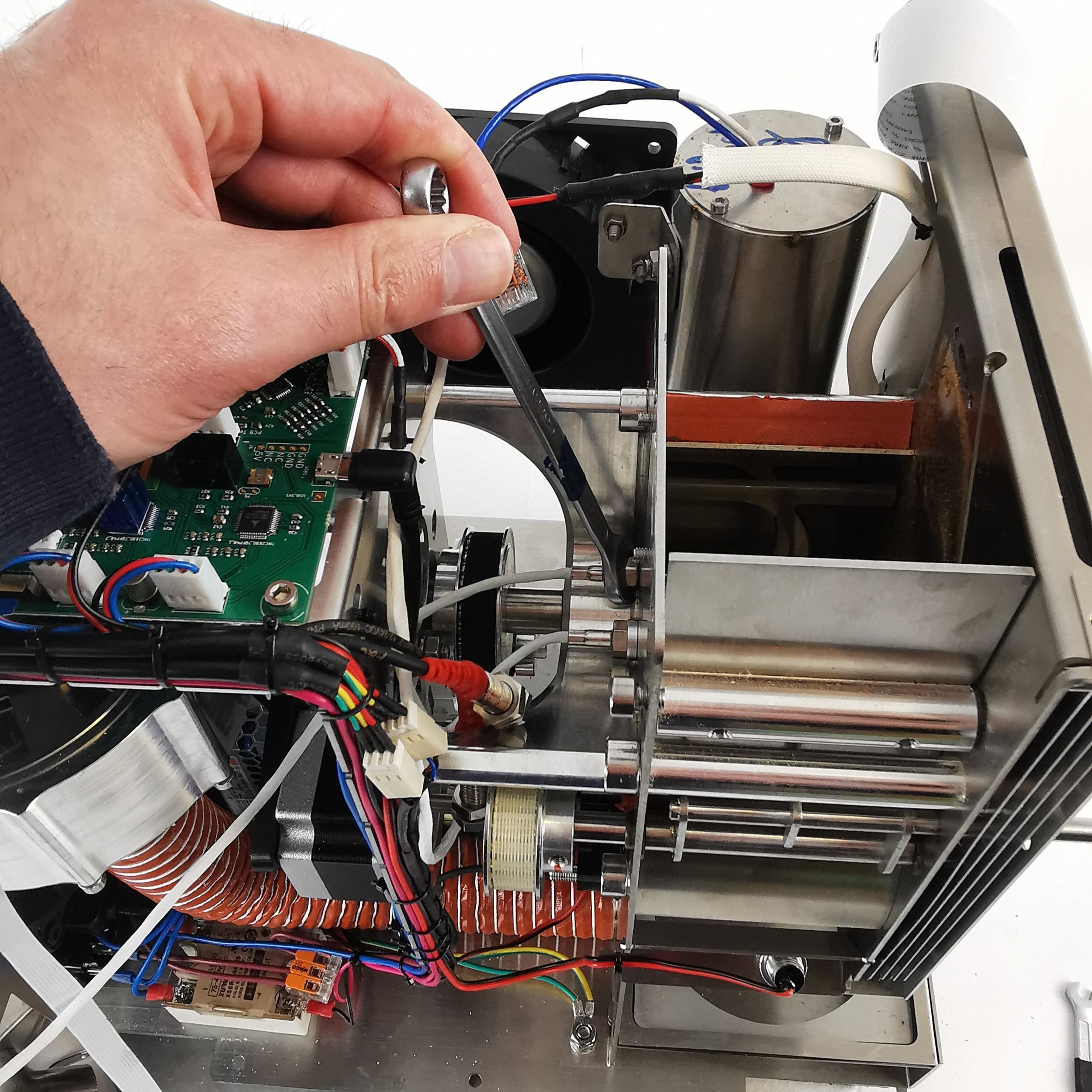
3. If your roaster has First Crack detection, you can optionally remove it for easier access. To do so, pull the card gently off the rubber mounts. Leave the cable connected and place the card to one side.

4. Unplug the Exhaust Temperature sensor from the PCB.
5. Cut the cable ties holding the cable in place.
6. Use a 10-millimeter spanner/wrench to loosen the exhaust sensor, and unscrew the sensor from the drum to remove it.
7. Take off the aluminum spacer from the old sensor, and replace it on the new sensor.

8. Screw the new sensor into the back plate by hand until finger tight. NOTE: Please ensure no resistance when rotating so as not to damage the thread in the back plate.
9. Tighten gently with a 10-millimeter wrench. Do not overtighten, as this can strip the thread and scrap the back plate.
10. Feed the cable from the new sensor into position. Pass the cable alongside the other white sensor cables, behind the USB cable, then connect it to the PCB.
11. Tie two new cable ties to the motor bracket where you removed the cable ties earlier.
NOTE: Cable should not touch rotating pulley. This can damage/destroy the sensor over time.
Use cutters to trim excess ends on cable ties.
12. Re-install FC card.

a. Push FC card into position. Pull gently on the ends of the rubber mounts to secure them in place.

b. First Crack card should NOT touch the back plate of the roaster.
24. Install side panels.
26. Plug the roaster in, turn it on and test the exhaust temperature sensor by starting a roast (beans in the machine). You should see the exhaust temperature appear on the graph in live view. If the exhaust temperature doesn’t appear, please double-check the connection to the PCB, and then contact the ROEST support team for help.
How to change: BT temperature sensor

Where to buy temperature sensors?
If you are sure that a temperature sensor in your roaster is broken (you have talked to our Support Team) visit our e-shop to purchase a new one!
Before you start
⚠️DISCLAIMER
Information in this document is believed to be accurate and reliable. However, the manufacturer does not give any representations or warranties, expressed or implied, as to the accuracy or completeness of such information and shall have no liability for the consequences of the use of such information. The manufacturer is not liable or responsible for any problems arising from the attempted repair. The manufacturer reserves the right to make changes to information published in this document, including without limitation specifications and product descriptions, at any time and without notice. The manufacturer's products are not designed, authorized, or warranted to be suitable for use in applications where failure or malfunction can reasonably be expected to result in personal injury, death, or severe property or environmental damage. The manufacturer accepts no liability for inclusion and/or use of its products in such equipment or applications and therefore such inclusion and/or use is for the customer’s own risk.
⚠️SAFETY INSTRUCTIONS
make sure the roaster is turned off
the power cord has to be unplugged
follow the steps as instructed below
Tools

Cutters

10-millimeter wrench
Parts

BT Sensor
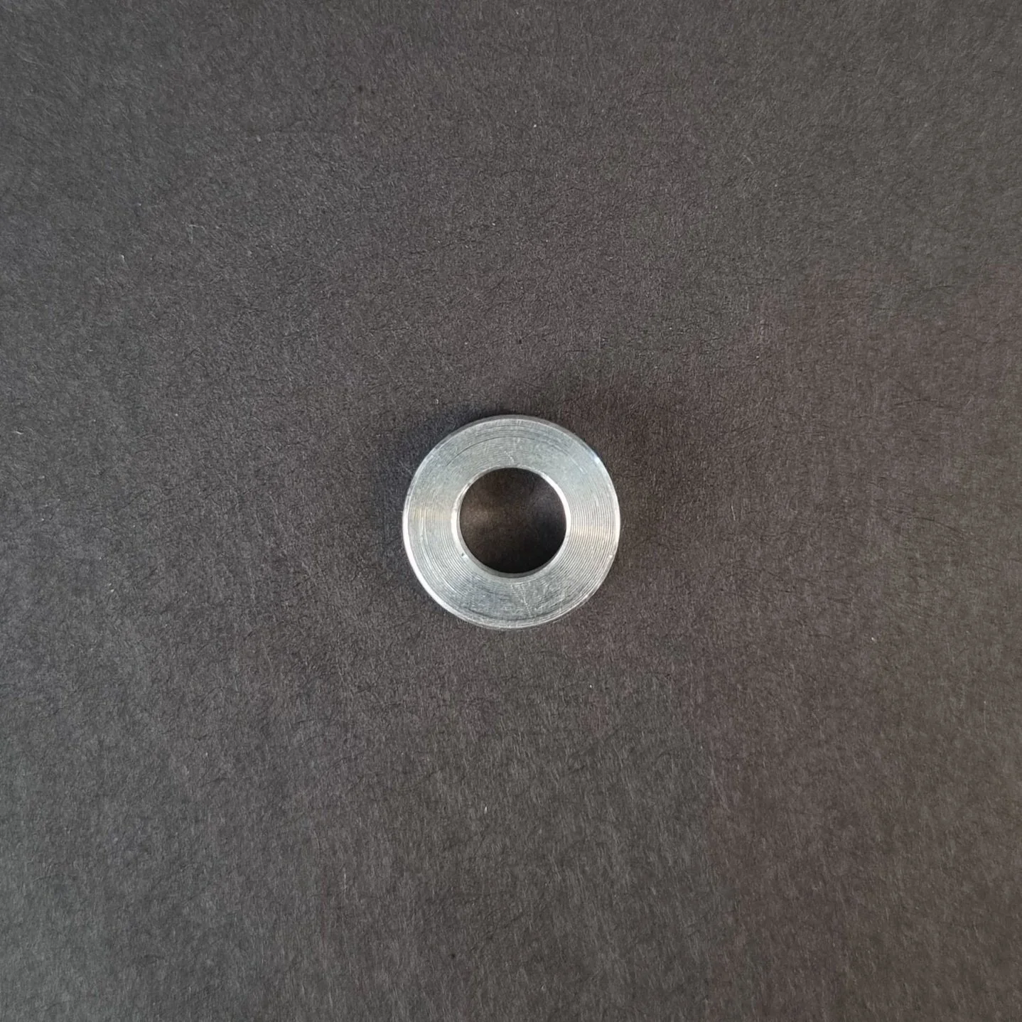
Aluminum Spacer. You will find this on the old sensor.
Cable Ties
Instructions
Follow this numbered guide below step by step.
3. Take a photo/make a reference of cable locations on the PCB so you can reinstall the cables in the correct position.

4. Remove the BT cable from the PCB.

1. Unplug the BT sensor

2. Unplug the USB1 cable

3. Let the BT sensor come out and plug in the USB cable
5. Cut cable ties holding the BT sensor to the motor bracket.

6. Loosen the BT sensor with a 10-millimeter wrench and remove it from the back plate.

7. Take off the aluminum spacer from the BT sensor.
8. Place the aluminum spacer on the new BT Sensor.
9. Locate the BT sensor in its threaded hole by hand, ensuring that the aluminum spacer stays on the BT sensor and continue until finger tight.

NOTE: when rotating the BT sensor by hand, ensure that there is little resistance so as not to damage the thread.
10. Tighten with a 10-millimeter wrench. Do not overtighten, as this can strip the thread and scrap the back plate.
11. Plug BT Sensor into the original spot within the PCB.
12. Tie the remaining cable to the motor bracket in the original place
NOTE: The cable should not touch the rotating pulley. This can damage/destroy the sensor over time.

13. Install side panels.
15. Plug the roaster in, turn it on and test the BT temperature sensor. If you read NaN on the touchscreen, something is wrong. If it doesn’t work, contact the ROEST support team.
How to change: ET temperature sensor
How to change the ET temperature sensors on your ROEST.
Where to buy temperature sensors?
If you are sure that a temperature sensor in your roaster is broken (you have talked to our Support Team) visit our e-shop to purchase a new one!
Before you start
⚠️DISCLAIMER
Information in this document is believed to be accurate and reliable. However, the manufacturer does not give any representations or warranties, expressed or implied, as to the accuracy or completeness of such information and shall have no liability for the consequences of the use of such information. The manufacturer is not liable or responsible for any problems arising from the attempted repair. The manufacturer reserves the right to make changes to information published in this document, including without limitation specifications and product descriptions, at any time and without notice. The manufacturer's products are not designed, authorized, or warranted to be suitable for use in applications where failure or malfunction can reasonably be expected to result in personal injury, death, or severe property or environmental damage. The manufacturer accepts no liability for inclusion and/or use of its products in such equipment or applications and therefore such inclusion and/or use is for the customer’s own risk.
⚠️SAFETY INSTRUCTIONS
make sure the roaster is turned off
the power cord has to be unplugged
follow the steps as instructed below
Tools
6-millimeter, 10-millimeter and 12-millimeter wrench

3-millimeter hexagonal key
Cutters

3-millimeter hexagonal tool bit

Small ratchet
Parts
ET sensor
Cable ties
Tray, or similar, to keep removed components
Instructions
Follow this numbered guide below step by step.
3. If your roaster has First Crack detection, remove it by pulling it gently and disconnecting the cable from the PCB.

4. Using the 12-millimeter wrench, remove the proximity sensors from the drop door. These can be left cabled into the roaster but moved out of the way for easy access.

5. Remove the charge handle.

6. Remove the exhaust pipe from the bean stopper exhaust (top) and chaff separator (bottom).


7. Using a 6-millimeter wrench, remove three off black First Crack “grommets”.


8. Remove the M4 x 6 Cap head screw holding the bean-stopper using the small ratchet with a 3-millimeter hexagonal tool bit.


9. Using a 3-millimeter hexagonal key, loosen and remove four off M4 x 6 cap head screws retaining the bean-stopper in position.

10. Once the screws from steps 8 and 9 have been removed, tilt the exhaust duct from the bean stopper upwards and pull the bean stopper out.


This will give you a clear view inside the roasting drum to install the new ET sensor.

11. Unplug the ET sensor from the PCB.

12. Cut cable ties holding the cable in place (two). Use the cutters.


13. Use a 10-millimeter spanner/wrench to loosen the M6 hexagonal nut holding the ET sensor in place.

14. Remove the ET sensor.
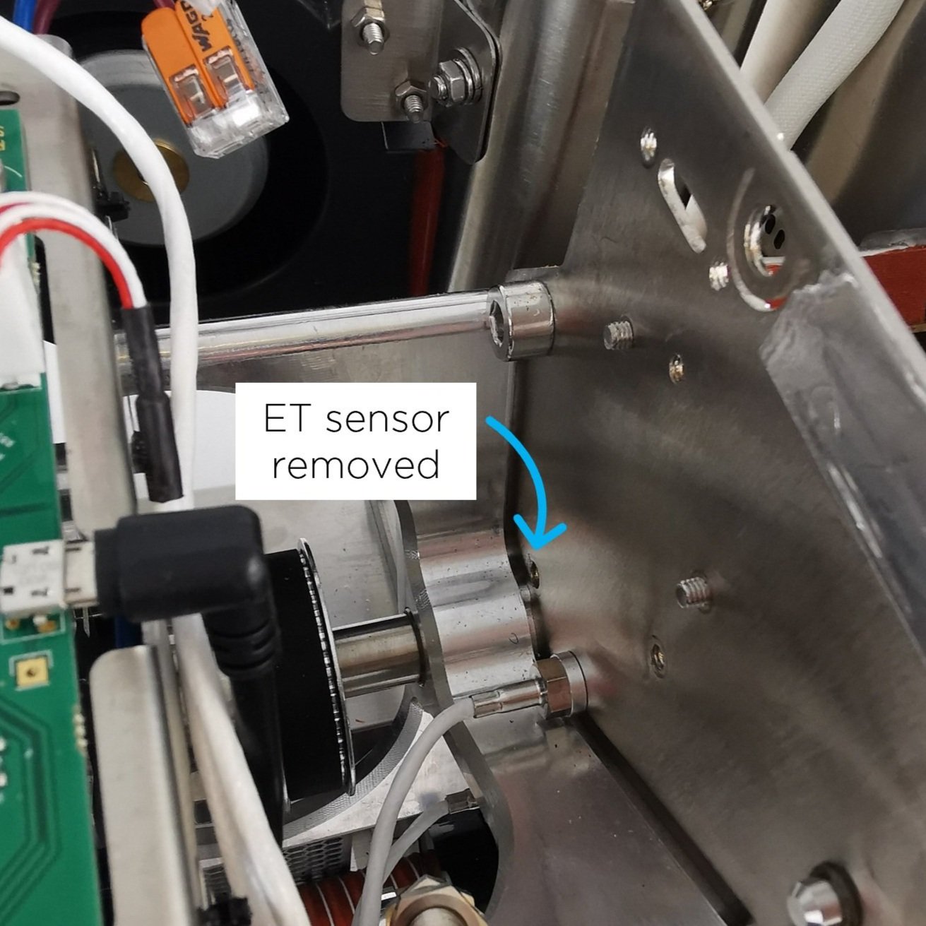
15. Take the new ET sensor and screw the M6 hexagonal nut onto the thread. The sensor should have a blacked-out area to indicate the length at which the sensor should be positioned in the drum.

16. Screw the ET sensor into the back plate. NOTE: Please ensure no resistance when rotating so as not to damage the thread in the back plate.

17. Before fastening, the orientation of the sensor is critical for it to work. From the front of the roaster, the orientation of the sensor must be as follows: The blue stripe should be on the right, and the white stripe in the middle should be completely vertical. If this criterion is met, fasten with the 10-millimeter wrench.
18. When fastening the sensor, ensure that nothing of the black area is visible inside the drum; if it is, you have screwed the sensor too far in.
19. If the criterion from steps 17 and 18 have been met, the nut can be tightened. Do not move forward until the orientation and length of the sensor have been set correctly.
20. Plug the ET sensor into the original spot on the PCB.

21. Tie two new cable ties to the motor bracket where you removed the cable ties earlier.


NOTE: Cable should not touch rotating pulley. This can damage/destroy the sensor over time.
22. Use cutters to trim excess ends on cable ties.

23. Continue to reassemble.

1. Push exhaust duct to original position

2. Tighten screws retaining bean-stopper

3. Install screw holding bean-stopper

4. Tighten FC grommets

5. Install exhaust pipe

6. Install charge handle

7. Screw the drop door sensors
8. Install FC card

9. Plug FC cable into PCB
10. First Crack card should NOT touch the back plate of the roaster.
24. Install side panels.
26. Plug the roaster in, turn it on and test the ET temperature sensor. Something is wrong if you see NaN on the touchscreen instead of a temperature where you normally read the ET temperature. Please contact the ROEST support team.
-
Adjustable roasting parameters
Service menu - includes recommended settings for motor gear ratio, cooling fan, heater fan, and PID settings.
-