
How to change: BT temperature sensor

Where to buy temperature sensors?
If you are sure that a temperature sensor in your roaster is broken (you have talked to our Support Team) visit our e-shop to purchase a new one!
Before you start
⚠️DISCLAIMER
Information in this document is believed to be accurate and reliable. However, the manufacturer does not give any representations or warranties, expressed or implied, as to the accuracy or completeness of such information and shall have no liability for the consequences of the use of such information. The manufacturer is not liable or responsible for any problems arising from the attempted repair. The manufacturer reserves the right to make changes to information published in this document, including without limitation specifications and product descriptions, at any time and without notice. The manufacturer's products are not designed, authorized, or warranted to be suitable for use in applications where failure or malfunction can reasonably be expected to result in personal injury, death, or severe property or environmental damage. The manufacturer accepts no liability for inclusion and/or use of its products in such equipment or applications and therefore such inclusion and/or use is for the customer’s own risk.
⚠️SAFETY INSTRUCTIONS
make sure the roaster is turned off
the power cord has to be unplugged
follow the steps as instructed below
Tools

Cutters

10-millimeter wrench
Parts

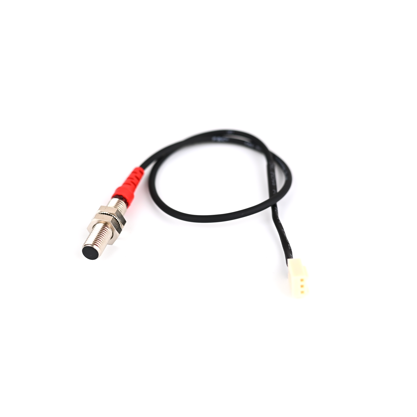
BT Sensor
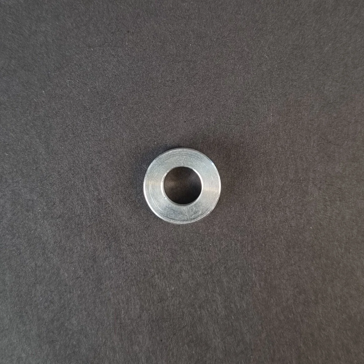
Aluminum Spacer. You will find this on the old sensor.

Cable Ties
Instructions
Follow this numbered guide below step by step.
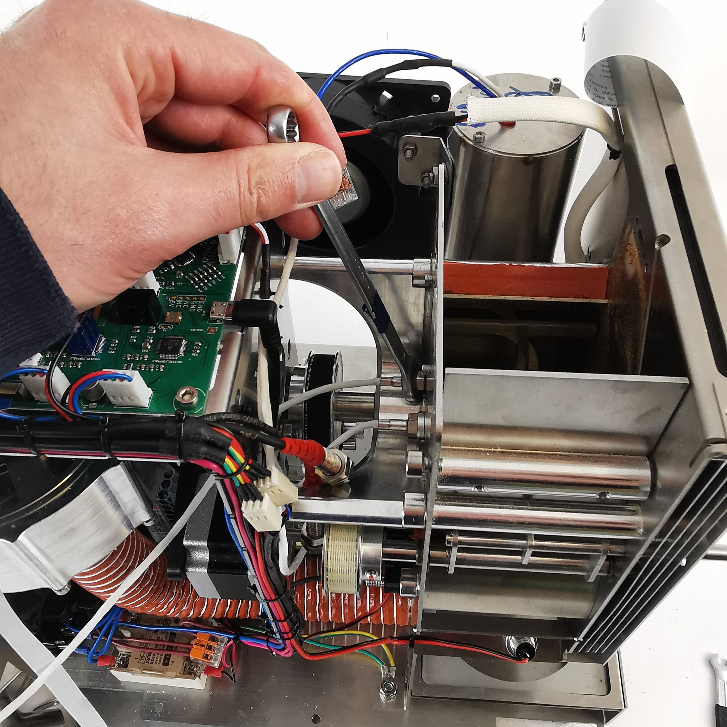
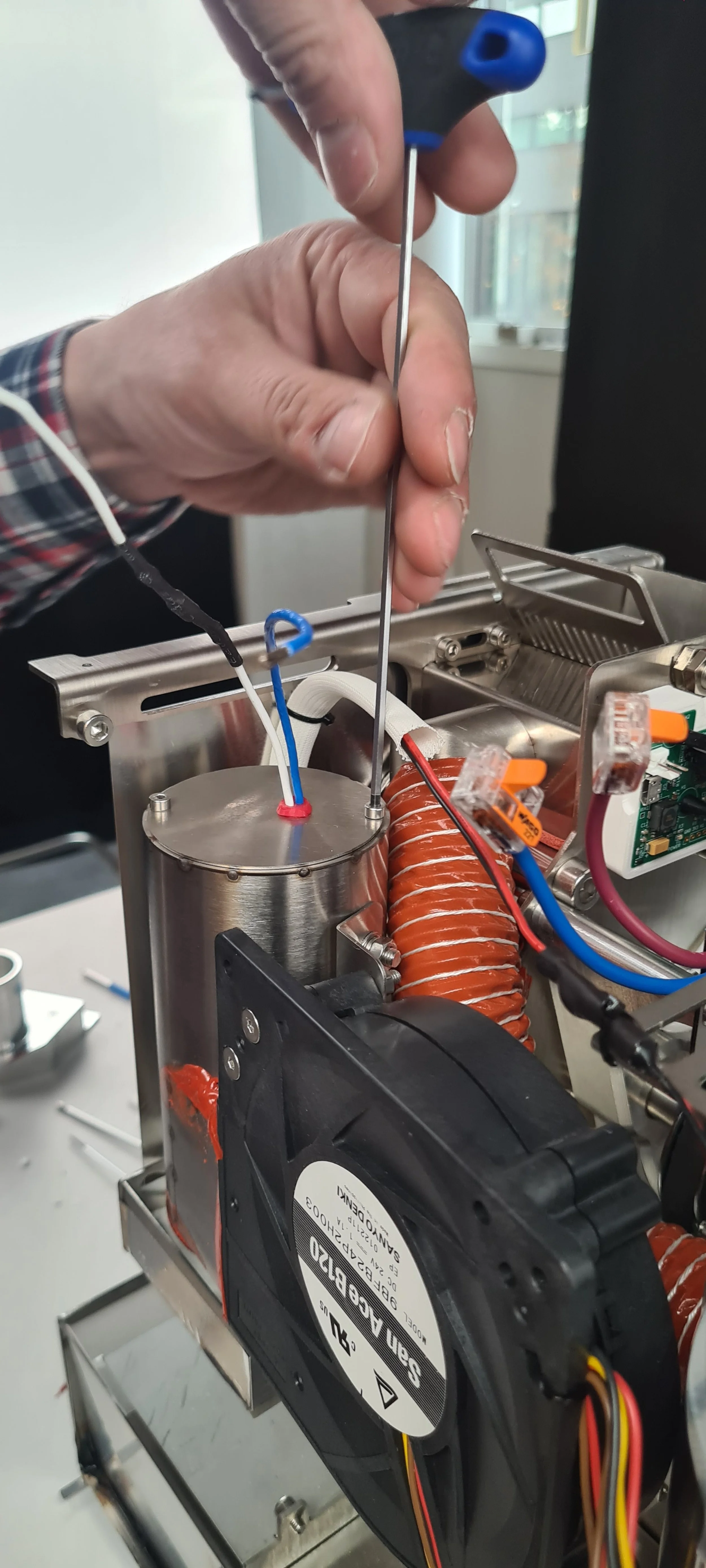
3. Take a photo/make a reference of cable locations on the PCB so you can reinstall the cables in the correct position.

4. Remove the BT cable from the PCB.

1. Unplug the BT sensor

2. Unplug the USB1 cable

3. Let the BT sensor come out and plug in the USB cable
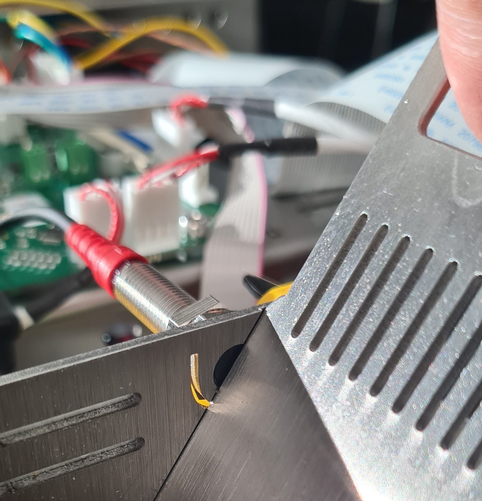
5. Cut cable ties holding the BT sensor to the motor bracket.

6. Loosen the BT sensor with a 10-millimeter wrench and remove it from the back plate.

7. Take off the aluminum spacer from the BT sensor.

8. Place the aluminum spacer on the new BT Sensor.
9. Locate the BT sensor in its threaded hole by hand, ensuring that the aluminum spacer stays on the BT sensor and continue until finger tight.

NOTE: when rotating the BT sensor by hand, ensure that there is little resistance so as not to damage the thread.
10. Tighten with a 10-millimeter wrench. Do not overtighten, as this can strip the thread and scrap the back plate.
11. Plug BT Sensor into the original spot within the PCB.
12. Tie the remaining cable to the motor bracket in the original place
NOTE: The cable should not touch the rotating pulley. This can damage/destroy the sensor over time.

13. Install side panels.
15. Plug the roaster in, turn it on and test the BT temperature sensor. If you read NaN on the touchscreen, something is wrong. If it doesn’t work, contact the ROEST support team.
How to change: ET temperature sensor
How to change the ET temperature sensors on your ROEST.

Where to buy temperature sensors?
If you are sure that a temperature sensor in your roaster is broken (you have talked to our Support Team) visit our e-shop to purchase a new one!
Before you start
⚠️DISCLAIMER
Information in this document is believed to be accurate and reliable. However, the manufacturer does not give any representations or warranties, expressed or implied, as to the accuracy or completeness of such information and shall have no liability for the consequences of the use of such information. The manufacturer is not liable or responsible for any problems arising from the attempted repair. The manufacturer reserves the right to make changes to information published in this document, including without limitation specifications and product descriptions, at any time and without notice. The manufacturer's products are not designed, authorized, or warranted to be suitable for use in applications where failure or malfunction can reasonably be expected to result in personal injury, death, or severe property or environmental damage. The manufacturer accepts no liability for inclusion and/or use of its products in such equipment or applications and therefore such inclusion and/or use is for the customer’s own risk.
⚠️SAFETY INSTRUCTIONS
make sure the roaster is turned off
the power cord has to be unplugged
follow the steps as instructed below
Tools

6-millimeter, 10-millimeter and 12-millimeter wrench

3-millimeter hexagonal key

Cutters

3-millimeter hexagonal tool bit

Small ratchet
Parts

ET sensor
Cable ties

Tray, or similar, to keep removed components
Instructions
Follow this numbered guide below step by step.
3. If your roaster has First Crack detection, remove it by pulling it gently and disconnecting the cable from the PCB.


4. Using the 12-millimeter wrench, remove the proximity sensors from the drop door. These can be left cabled into the roaster but moved out of the way for easy access.

5. Remove the charge handle.

6. Remove the exhaust pipe from the bean stopper exhaust (top) and chaff separator (bottom).


7. Using a 6-millimeter wrench, remove three off black First Crack “grommets”.


8. Remove the M4 x 6 Cap head screw holding the bean-stopper using the small ratchet with a 3-millimeter hexagonal tool bit.


9. Using a 3-millimeter hexagonal key, loosen and remove four off M4 x 6 cap head screws retaining the bean-stopper in position.

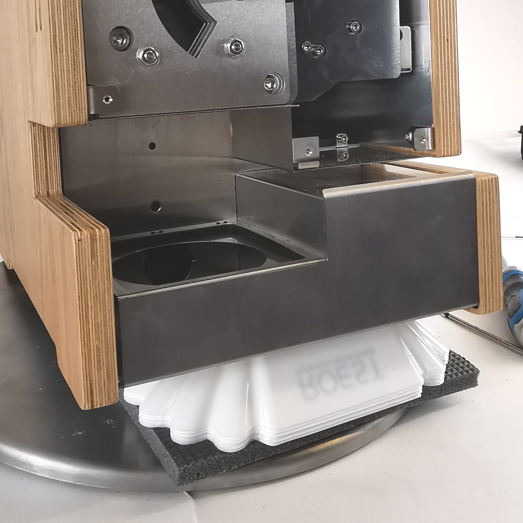
10. Once the screws from steps 8 and 9 have been removed, tilt the exhaust duct from the bean stopper upwards and pull the bean stopper out.


This will give you a clear view inside the roasting drum to install the new ET sensor.

11. Unplug the ET sensor from the PCB.

12. Cut cable ties holding the cable in place (two). Use the cutters.


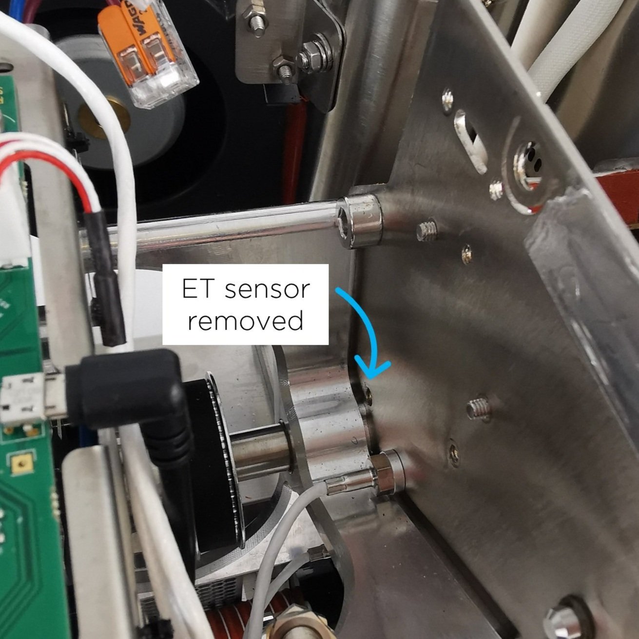
13. Use a 10-millimeter spanner/wrench to loosen the M6 hexagonal nut holding the ET sensor in place.

14. Remove the ET sensor.
15. Take the new ET sensor and screw the M6 hexagonal nut onto the thread. The sensor should have a blacked-out area to indicate the length at which the sensor should be positioned in the drum.

16. Screw the ET sensor into the back plate. NOTE: Please ensure no resistance when rotating so as not to damage the thread in the back plate.

17. Before fastening, the orientation of the sensor is critical for it to work. From the front of the roaster, the orientation of the sensor must be as follows: The blue stripe should be on the right, and the white stripe in the middle should be completely vertical. If this criterion is met, fasten with the 10-millimeter wrench.
18. When fastening the sensor, ensure that nothing of the black area is visible inside the drum; if it is, you have screwed the sensor too far in.
19. If the criterion from steps 17 and 18 have been met, the nut can be tightened. Do not move forward until the orientation and length of the sensor have been set correctly.
20. Plug the ET sensor into the original spot on the PCB.

21. Tie two new cable ties to the motor bracket where you removed the cable ties earlier.


NOTE: Cable should not touch rotating pulley. This can damage/destroy the sensor over time.
22. Use cutters to trim excess ends on cable ties.

23. Continue to reassemble.

1. Push exhaust duct to original position

2. Tighten screws retaining bean-stopper

3. Install screw holding bean-stopper

4. Tighten FC grommets

5. Install exhaust pipe

6. Install charge handle

7. Screw the drop door sensors

8. Install FC card

9. Plug FC cable into PCB

10. First Crack card should NOT touch the back plate of the roaster.
24. Install side panels.
26. Plug the roaster in, turn it on and test the ET temperature sensor. Something is wrong if you see NaN on the touchscreen instead of a temperature where you normally read the ET temperature. Please contact the ROEST support team.
How to change: Drum window LED light
How to change the LED light of the drum window on your ROEST.

Where to buy drum window LED light?
If you are sure the LED light of the drum window is broken (you have talked to our Support Team) visit our e-shop to purchase a new one!
Before you start
⚠️DISCLAIMER
Information in this document is believed to be accurate and reliable. However, the manufacturer does not give any representations or warranties, expressed or implied, as to the accuracy or completeness of such information and shall have no liability for the consequences of the use of such information. The manufacturer is not liable or responsible for any problems arising from the attempted repair. The manufacturer reserves the right to make changes to information published in this document, including without limitation specifications and product descriptions, at any time and without notice. The manufacturer's products are not designed, authorized, or warranted to be suitable for use in applications where failure or malfunction can reasonably be expected to result in personal injury, death, or severe property or environmental damage. The manufacturer accepts no liability for inclusion and/or use of its products in such equipment or applications and therefore such inclusion and/or use is for the customer’s own risk.
⚠️SAFETY INSTRUCTIONS
make sure the roaster is turned off
the power cord has to be unplugged
follow the steps as instructed below
Tools

10-millimeter spanner/wrench/socket

2-millimeter hexagonal key

Cutters

Bean sample tray or similar, to prop the roaster at an angle for easy of disassembling
Parts

Plate 3 with LED light attached

Cable ties
Instructions
Step-by-step guide:
2. Remove the front décor plate.
3. Orientate the roaster so that the front is facing you. Lift the front of the roaster and place an item underneath to tilt the roaster back (for this example we have used a few sample trays).

This is to give adequate access to the window LED and to enable the removal of aluminum spacers easier.
4. Remove the LED cable from the PCB and cut any cable ties securing it to the motor bracket.


5. Remove the protective sleeve and keep it for reinstallation. NOTE: if the protective sleeve is damaged, e.g., if a cable can be seen through the sleeve, discard it.

6. Pull the LED cable through the hole located in plate 1.


7. Remove the 6-millimeter nuts. Use the 10-millimeter wrench to loosen them and unscrew them by hand.


8. Remove plate 4 and the four aluminum spacers behind it.

1. Plate 4 removal
2. Take off the spacers
9. Remove plate 3 with the old LED light.

Plate 3 removal

This plate can be scrapped. Separate the metal part from the electronic part, and dispose of it responsibly.
NOTE: Check if the aluminum spacer is stuck to the backside of “Plate 3”; remove the spacer if it has adhered to the aluminum tape.
10. Install the new plate 3 with LED.
1. Ensure that the four aluminum spacers are on top of plate 2.

2. Install the new plate 3 and leave the cable loose.
11. Install the four aluminum spacers on top of Plate 3.
12. Install plate 4.
Install the four nuts and tighten them with the 10-millimeter wrench. NOTE: do not over-tighten the nuts, as this could damage the threads and the subsequent plates.

13. Feed the LED cable through the hole in plate 1 (this plate is the widest of the four plates).

14. Feed the protective sleeve over the end of the LED cable where it should touch the backside of plate 1.


15. Cable tie the protective sleeve and LED cable to plate 1.

Cable tie the sleeve at the top of plate one.
16. Plug the LED cable back into the original location on the PCB. NOTE: the PCB location reads “LED2”.

17. Tie loose cables to the motor bracket.

18. Install front décor plate.
20. Plug the roaster in, turn it on and test the drum window LED light. If it doesn’t work, contact the ROEST support team.
Video instructions
How to remove and install front décor plate

Before you start
⚠️DISCLAIMER
Information in this document is believed to be accurate and reliable. However, the manufacturer does not give any representations or warranties, expressed or implied, as to the accuracy or completeness of such information and shall have no liability for the consequences of the use of such information. The manufacturer is not liable or responsible for any problems arising from the attempted repair. The manufacturer reserves the right to make changes to information published in this document, including without limitation specifications and product descriptions, at any time and without notice. The manufacturer's products are not designed, authorized, or warranted to be suitable for use in applications where failure or malfunction can reasonably be expected to result in personal injury, death, or severe property or environmental damage. The manufacturer accepts no liability for inclusion and/or use of its products in such equipment or applications and therefore such inclusion and/or use is for the customer’s own risk.
⚠️SAFETY INSTRUCTIONS
make sure the roaster is turned off
the power cord has to be unplugged
follow the steps as instructed below
Tools

2 and 3-millimeter hexagonal tool
How to remove front décor plate
1a. Pull out the trier and the drop handle.
The black drop handle is attached by a set screw. Use the 3-millimeter hexagonal tool to remove it.


For the wooden drop handle, just pull it to take it off.
2. Disconnect the touchscreen cable from PCB. Push back the black retaining clip and detach the cable. Ensure the retaining clip is left in place at the connection point.


3. Remove the three front plate screws by using the 2-millimeter hexagonal tool.

4. Slowly remove the front décor plate from the roaster. Take off the front décor plate and place it on a protective surface. Leave the 40-pin cable connected to the screen.


How to install front décor plate
1. Feed the touchscreen cable through the original slots on the roaster and put the front décor plate in its position.

1. Cable through the frontal slot

2. Front décor plate installation

3. Cable through the top slot
2. Install the touchscreen cable into the PCB. Push the black retaining clip and insert the cable (you must twist it to show the blue band of the cable facing up).

You can use a flat head screwdriver to keep the clip “open” while inserting the cable.

Once in position, fasten it by pushing the clip back to its original position.
3. Install three M3 x 6 countersunk screws into the front décor plate by using the 2-millimeter hexagonal key.

4. Install the drop handle and the trier. For a wooden handle, push it through. For a black drop handle install the set screw using the 2-millimeter hexagonal tool.

How to change: Bean cooler LED light
How to replace a touch screen on your ROEST.

Where to buy LED light?
If you are sure your LED-light is broken (you have talked to our Support Team) visit our e-shop to purchase a new one!
Before you start
⚠️DISCLAIMER
Information in this document is believed to be accurate and reliable. However, the manufacturer does not give any representations or warranties, expressed or implied, as to the accuracy or completeness of such information and shall have no liability for the consequences of the use of such information. The manufacturer is not liable or responsible for any problems arising from the attempted repair. The manufacturer reserves the right to make changes to information published in this document, including without limitation specifications and product descriptions, at any time and without notice. The manufacturer's products are not designed, authorized, or warranted to be suitable for use in applications where failure or malfunction can reasonably be expected to result in personal injury, death, or severe property or environmental damage. The manufacturer accepts no liability for inclusion and/or use of its products in such equipment or applications and therefore such inclusion and/or use is for the customer’s own risk.
⚠️SAFETY INSTRUCTIONS
make sure the roaster is turned off
the power cord has to be unplugged
follow the steps as instructed below
Tools

Cutters
Parts

Bean cooler LED assembly

Cable ties to re-cable the LED light to the motor bracket.
Instructions
Step-by-step guide:
1. Remove the top plate. You can read how to do it here.
2. Remove the left side panel. Click here to see how to do it.
3. To know where to relocate and fasten the new LED light, you can take a photo of the cable location on the PCB (connector named LED1 on the PCB) and how cables are fastened to the motor bracket.

From top

From side
4. Disconnect bean cooler LED light cable from PCB.

5. Remove the old Bean Cooler LED Assembly. NOTE: if the LED is damaged, disassemble it from the bracket and dispose of it responsibly.


6. Cut cable ties to release LED cable by using the cutters.
CAUTION! take care not to cut through any cables. NOTE: Only cut the number of cable ties required to release that cable.


7. Slide the new bean cooler LED into position. NOTE: if the component does not locate by hand, gently tap the component into place until seated.


8. Plug the cable back into the PCB slot (connector named LED1).

9. Start tying the LED cable into position. Tie the LED cable into the remaining cables along the motor bracket.

Ensure that the cable has been fastened in position with a loop. This is in case the PCB needs to be changed.

IMPORTANT: Ensure that proximity extension cables are not cable tied.
10. Trim the excess from cable ties by using the cutters.
11. Before putting the left side panel and top plate back on the roaster, ensure that there is no excess cable from Bean Cooler LED Assembly that can be squeezed and damaged. IMPORTANT: If there is excess cable when the left side panel is fastened in place, this can cause the cable to become damaged and cause electrical faults in the roaster.

LED cable should look like this (no excess)
12. Install the left side panel.
13. Install the top plate.
14. Plug the roaster in, turn it on and test the LED light. If it doesn’t work, contact the ROEST support team.
How to change: PCB encoder
This is the guide on how to change the PCB encoder on your ROEST.

Where to buy PCB encoder?
If you are sure your encoder is broken (you have talked to our Support Team) visit our e-shop to purchase a new one!
Before you start
⚠️DISCLAIMER
Information in this document is believed to be accurate and reliable. However, the manufacturer does not give any representations or warranties, expressed or implied, as to the accuracy or completeness of such information and shall have no liability for the consequences of the use of such information. The manufacturer is not liable or responsible for any problems arising from the attempted repair. The manufacturer reserves the right to make changes to information published in this document, including without limitation specifications and product descriptions, at any time and without notice. The manufacturer's products are not designed, authorized, or warranted to be suitable for use in applications where failure or malfunction can reasonably be expected to result in personal injury, death, or severe property or environmental damage. The manufacturer accepts no liability for inclusion and/or use of its products in such equipment or applications and therefore such inclusion and/or use is for the customer’s own risk.
⚠️SAFETY INSTRUCTIONS
make sure the roaster is turned off
the power cord has to be unplugged
follow the steps as instructed below
Tools

2-millimeter hexagonal key

10-millimeter spanner/wrench/socket
Parts

Encoder PCB
Instructions
Step-by-step guide:
1. Remove the top plate and cable. You can read how to do it here.
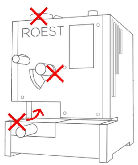
2. Place the top plate on a protective surface and loosen the “grub screw” on the encoder knob. Use the 2-millimeter hexagonal key.
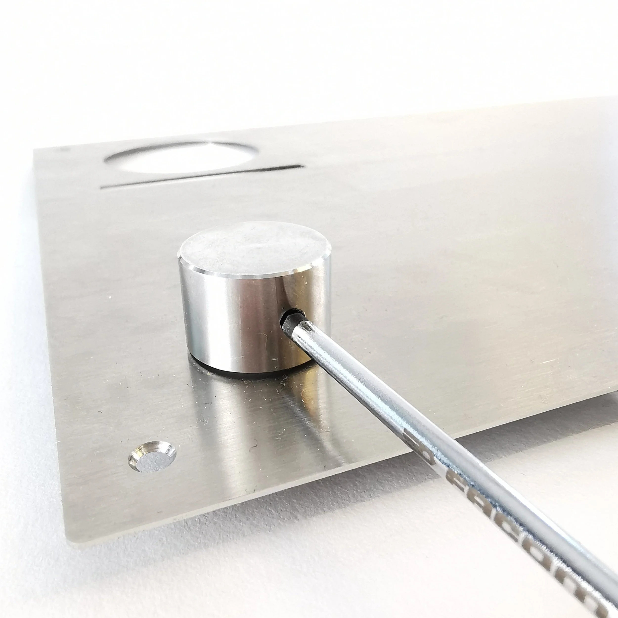
3. Remove the encoder knob and nylon washer.


4. Use the 10-millimeter spanner/wrench/socket to loosen the retaining nut and remove it. Take off the old encoder PCB and screw the nut back onto the threaded portion.
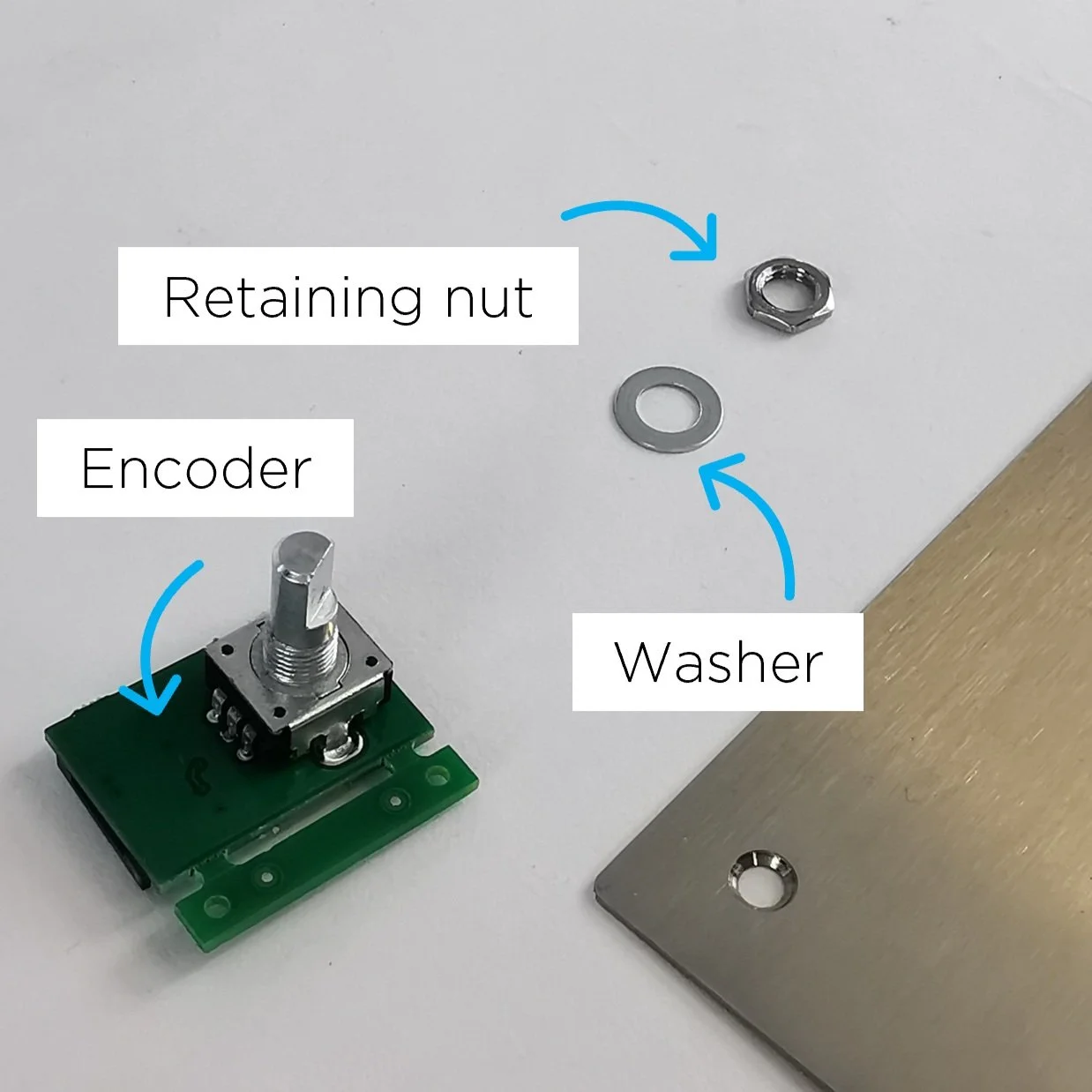
5. Take the new encoder PCB, and remove the retaining nut and the washer.
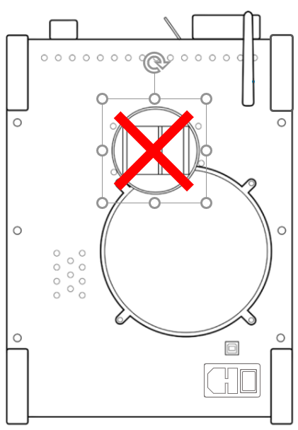
6. Locate the D-Shaped encoder PCB portion through the top plate hole.


7. Locate the washer and retaining nut on the threaded part (on the other side of the top plate).

First, fasten it by hand, and tighten it using the 10-millimeter wrench.

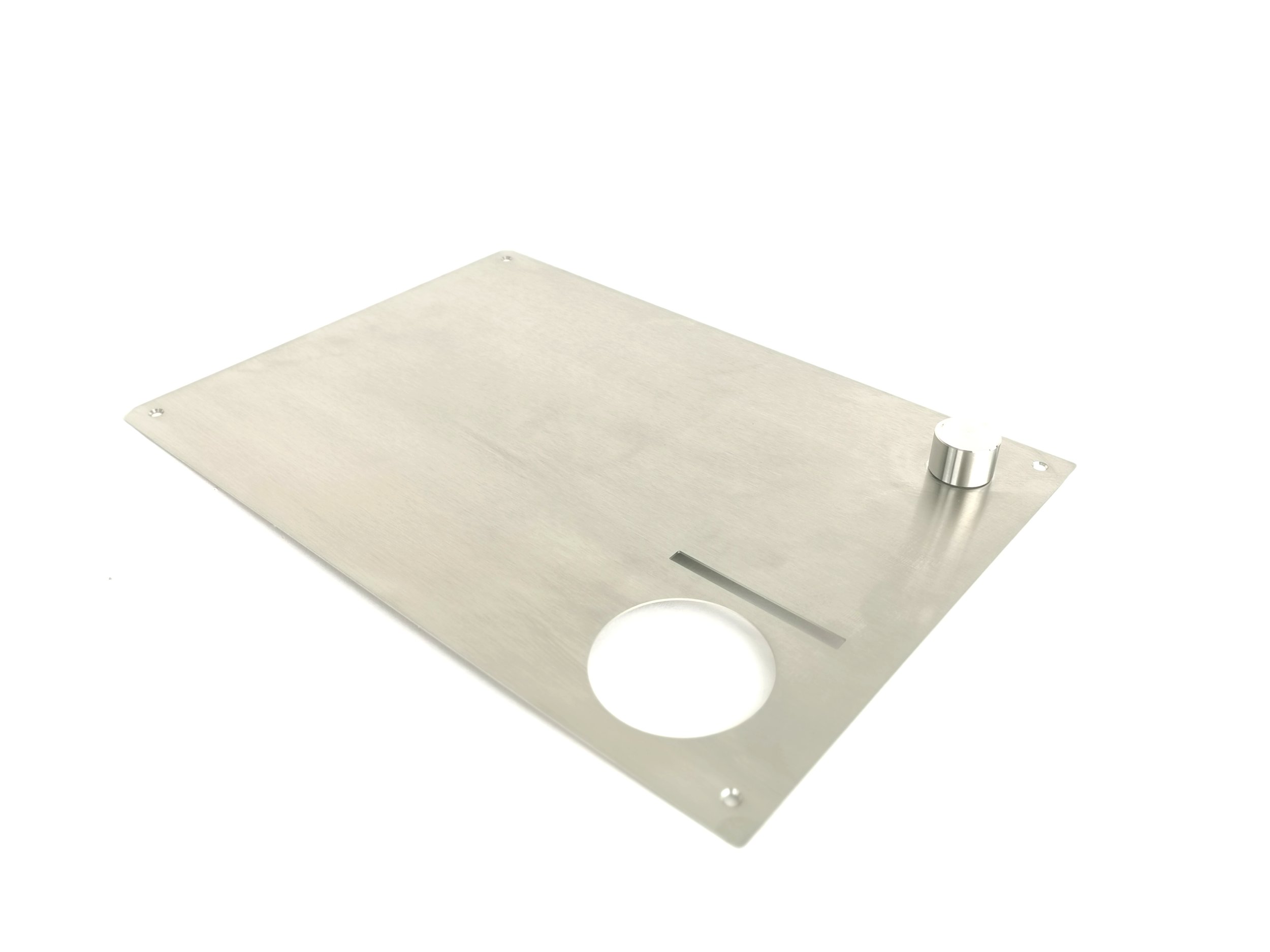
The orientation of the encoder must be as original. If not, the top plate will not fit. See D-shaped portion orientation.
8. Place the encoder knob (including the nylon washer) on top of the D-Shaped portion.

Align the grub screw hole with the flat portion of D Shape.

9. Tighten it by using the 2-millimeter hexagonal key.

10. Install the top plate and the encoder cable.
11. Plug the roaster in, turn it on and test the encoder. If it doesn’t work, contact the ROEST support team.
How to remove and install top plate
Before you start
⚠️DISCLAIMER
Information in this document is believed to be accurate and reliable. However, the manufacturer does not give any representations or warranties, expressed or implied, as to the accuracy or completeness of such information and shall have no liability for the consequences of the use of such information. The manufacturer is not liable or responsible for any problems arising from the attempted repair. The manufacturer reserves the right to make changes to information published in this document, including without limitation specifications and product descriptions, at any time and without notice. The manufacturer's products are not designed, authorized, or warranted to be suitable for use in applications where failure or malfunction can reasonably be expected to result in personal injury, death, or severe property or environmental damage. The manufacturer accepts no liability for inclusion and/or use of its products in such equipment or applications and therefore such inclusion and/or use is for the customer’s own risk.
⚠️SAFETY INSTRUCTIONS
make sure the roaster is turned off
the power cord has to be unplugged
follow the steps as instructed below
Tools

2-millimeter hexagonal tool
How to remove the top plate
Take off the hopper and follow the instruction below.
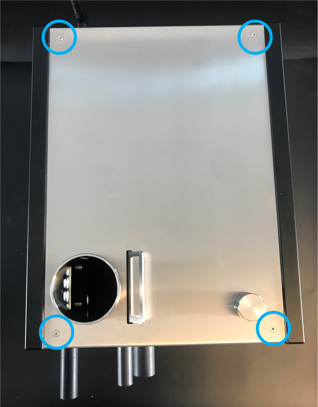
1. There are four screws on the top

2. Use the 2-millimeter hexagonal tool to remove them

3. Take off the plate slowly
5. Gently, lean the plate on the side of the roaster.
If you need to remove the cable attached to the encoder, push the black retaining clip and disconnect the cable.

The following video shows you how to remove the top plate.
How to install the top plate
If the encoder cable has been detached, you must connect it before you install the top plate. Push the black retaining clip and insert the cable through the slot.

Make sure the blue band on the cable is facing up.

Ensure the cable is inserted into the slot and the black retaining clip is fully fastened.
Now, install the top plate.

Follow this order to tighten the screws

Make sure to press front plate when installing screw 1 and 3
The following video shows you how to install the top plate.
How to change: S/L100 PCB
How to replace the PCB on your ROEST S100 or ROEST L100.

Where to request a new PCB?
If you are sure your PCB is not working well (you have talked to our Support Team), visit our e-shop to request a new one!
Before you start
⚠️DISCLAIMER
Information in this document is believed to be accurate and reliable. However, the manufacturer does not give any representations or warranties, expressed or implied, as to the accuracy or completeness of such information and shall have no liability for the consequences of the use of such information. The manufacturer is not liable or responsible for any problems arising from the attempted repair. The manufacturer reserves the right to make changes to information published in this document, including without limitation specifications and product descriptions, at any time and without notice. The manufacturer's products are not designed, authorized, or warranted to be suitable for use in applications where failure or malfunction can reasonably be expected to result in personal injury, death, or severe property or environmental damage. The manufacturer accepts no liability for inclusion and/or use of its products in such equipment or applications and therefore such inclusion and/or use is for the customer’s own risk.
⚠️SAFETY INSTRUCTIONS
make sure the roaster is turned off
the power cord has to be unplugged
follow the steps as instructed below
Tools
2-millimeter and 3-millimeter hexagonal tool
Parts

S100 or L100 PCB. On an L100 PCB, these two black chips must be present.
Instructions
Step-by-step guide:
1. Remove the top plate (remove the hopper before you start).
2. Take a photo or make a reference to the current location of the connections on the PCB. You can use tape or a marker (see the example below).


3. Disconnect all of the cables on the PCB. IMPORTANT! There is no need to cut any cable ties harnessing the cables to the motor bracket. You will detach the cables by pulling them back gently. Use a screwdriver for the following connectors:

Unscrew the bolts

L100: Unscrew the bolts

You can help yourself with a screwdriver to detach this little cable
For the two cables attached by a black retaining clip, push it back and detach the cable. Ensure the retaining clip is left in place at the connection point.


4. Unscrew four off M4 x 6 cap head bolts from the motor bracket. Use the 3-millimeter hexagonal tool.

5. Lift off the PCB slowly. CAUTION! Nylon washers located underneath the PCB could drop inside the machine if not handled carefully. Ensure that the four washers are placed over the threaded holes after this operation.

6. Remove the new PCB from the bag & place the old PCB in the bag.
7. Place the new PCB in the original position on the motor bracket. CAUTION! Operate gently to ensure the nylon washers do not fall into the roaster.
8. Secure with four off M4 x 6 cap head bolts.
9. Reconnect cables as per the image/reference taken.
IMPORTANT! To make L100 sensors work, the following connections are crucial:
- Drum temperature cable must be connected correctly to work.
Yellow cable = POSITIVE
Red cable = NEGATIVE


-Extra proximity sensor cable must be connected to the 4th proximity sensor slot on PCB reading “Sensor0”.

11. Plug the roaster in, turn it on and test if the PCB has been connected correctly. For L100; if the roaster shows “0” for the drum temperature on the touchscreen, then re-check if the drum temperature cables (step 9) are correctly installed and properly inserted.
12. Once the PCB is correctly installed, please contact the ROEST support team to let us know, so that we can change over to he new PCB in our system.
13. Once your machine is switched over to the new PCB, if you have any problems connecting to the Roest server then please reset the metadata on your roaster. Enter the service menu, tap on ‘Settings’, and then tap ‘Clear Metadata’.
If the roaster doesn’t work properly after following the above steps, contact the ROEST support team for help.
How to install: First Crack Detection
This is the guide on how to install the First Crack Detector on your ROEST.
Important note: Only models starting P11_ and higher can upgrade to the First Crack Detection system.

Where to buy First Crack Detection?
If you would like to install a First Crack Detection system on your roaster visit our e-shop to buy it!
Before you start
⚠️DISCLAIMER
Information in this document is believed to be accurate and reliable. However, the manufacturer does not give any representations or warranties, expressed or implied, as to the accuracy or completeness of such information and shall have no liability for the consequences of the use of such information. The manufacturer is not liable or responsible for any problems arising from the attempted repair. The manufacturer reserves the right to make changes to information published in this document, including without limitation specifications and product descriptions, at any time and without notice. The manufacturer's products are not designed, authorized, or warranted to be suitable for use in applications where failure or malfunction can reasonably be expected to result in personal injury, death, or severe property or environmental damage. The manufacturer accepts no liability for inclusion and/or use of its products in such equipment or applications and therefore such inclusion and/or use is for the customer’s own risk.
⚠️SAFETY INSTRUCTIONS
make sure the roaster is turned off
the power cord has to be unplugged
follow the steps as instructed below
Tools

3-millimeter hexagonal key

6-millimeter spanner/wrench
Parts

First Crack card

Three rubber First Crack card holders

Cable
Instructions
Follow this numbered guide below step by step.
Remove the top plate. You can read how to do it here.
Remove the blanking bolt by using the 3-millimeter hexagonal key.
Removing the blanking bolt is essential so the First Crack card works. If the bolt is not present, continue to step 3.

3. Install the three rubber First Crack holders. Tighten them with the 6-millimeter spanner. NOTE: if already present, continue to step 4.


4. Plug the cable into the back of the First Crack card.
5. Install the First Crack card with the cable attached. The card has been designed so it can only be installed one way.

Locate it through the rubber holders.

Hold the card and pull the rubber until the card “snaps” onto the rubber holders.
6. Check the distance of the installed First Crack.

The First Crack card should NOT touch the back plate of the roaster.
7. Install the cable into the PCB – the red strip of the cable coming out from the First Crack card should face the right-side panel (as you look at the roaster from the front). That same red line should face the back of the roaster when connected to the PCB.

Push the connector to attach the cable to the PCB

This is how it should look after installation
9. Turn on the roaster.
10. Turn on First Crack detection, by following these four quick steps here.
Now you can set the BT threshold and Trigger count parameters to your liking.
You can learn more about First Crack by reading this article.
IMPORTANT! The First Crack detection system will not operate if the card is installed incorrectly. If it doesn’t work, contact the ROEST support team.
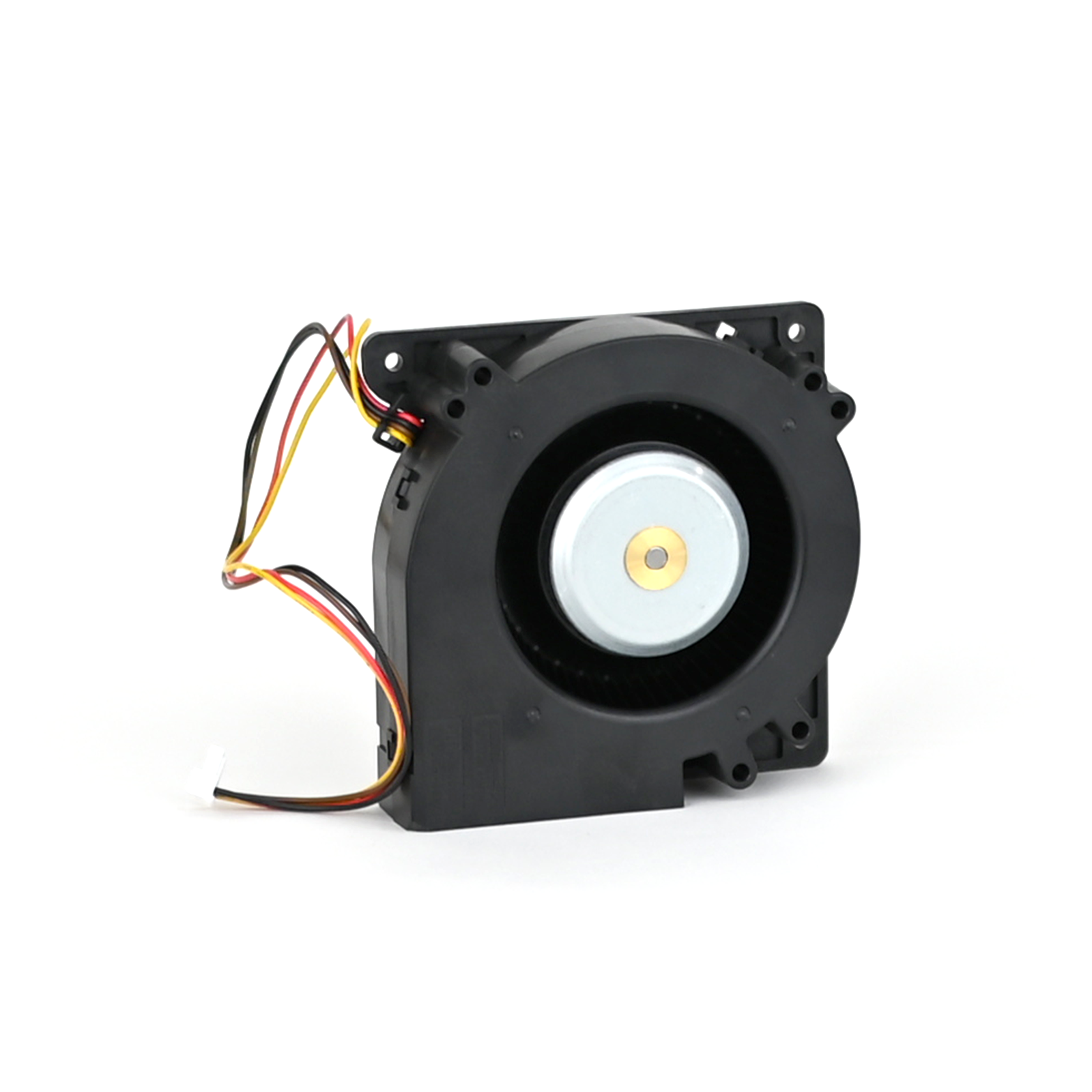
How to change: Heater fan
How to change the heater fan on your ROEST.
Where to buy heater fan?
If you are sure your heater fan is broken (you have talked to our Support Team) visit our e-shop to purchase a new one!
Before you start
⚠️DISCLAIMER
Information in this document is believed to be accurate and reliable. However, the manufacturer does not give any representations or warranties, expressed or implied, as to the accuracy or completeness of such information and shall have no liability for the consequences of the use of such information. The manufacturer is not liable or responsible for any problems arising from the attempted repair. The manufacturer reserves the right to make changes to information published in this document, including without limitation specifications and product descriptions, at any time and without notice. The manufacturer's products are not designed, authorized, or warranted to be suitable for use in applications where failure or malfunction can reasonably be expected to result in personal injury, death, or severe property or environmental damage. The manufacturer accepts no liability for inclusion and/or use of its products in such equipment or applications and therefore such inclusion and/or use is for the customer’s own risk.
⚠️SAFETY INSTRUCTIONS
make sure the roaster is turned off
the power cord has to be unplugged
follow the steps as instructed below
Tools
2.5-millimeter hexagonal key (L or T-shaped)
3-millimeter hexagonal key (T-shaped, long)
Stanley knife
Plastic gloves
Parts


NOTE: PCB reads “HeatFan2”
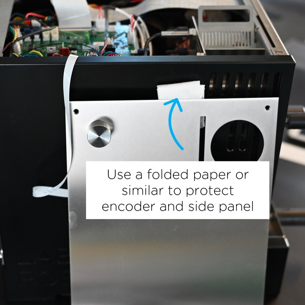
Disconnect the drum and inlet temperature sensor. This procedure is the same for both sensors.

Note how the wires are inserted into the screw terminal, the yellow wire is positive, and the red wire is negative.
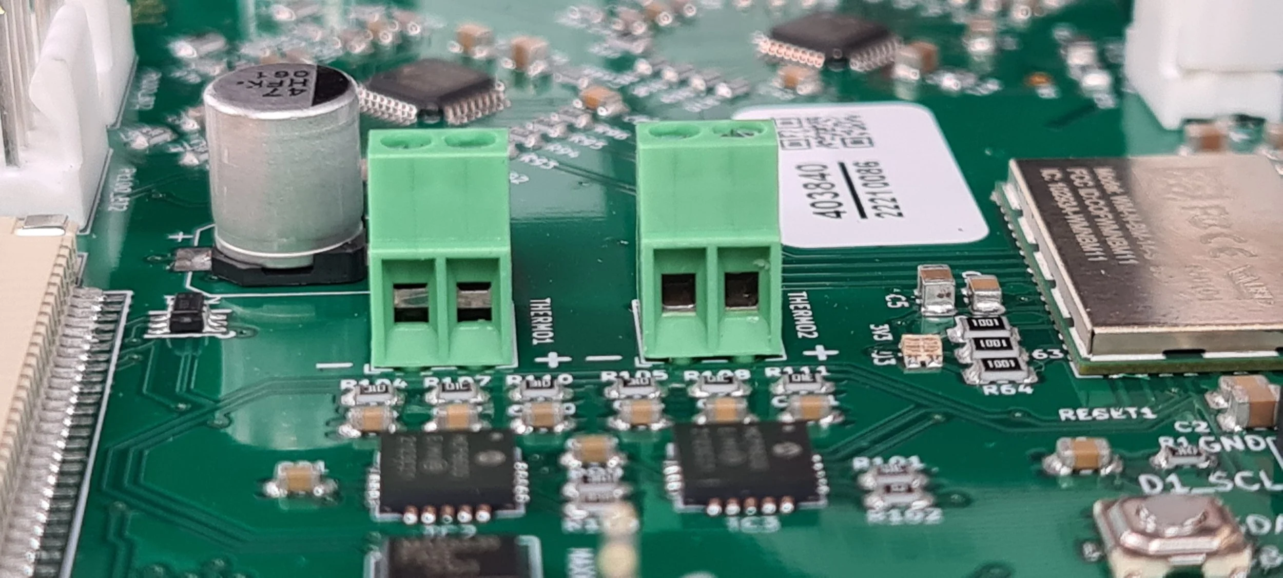
Make sure you open the hole up, as done on the right terminal. The left terminal is in the incorrect position.

Pull the cable through the holes in the heater fan.

Remove the cable completely from the heater fan.
5. Disconnect heating element cables from wago connectors and cut the cable ties. NOTE: Before disconnecting, take a photo or make a reference to ensure that the correct cable goes into the correct wago connector when reconnecting.

Cut the cable ties holding the cables from the heater fan in place. If you have extra, note how the cables are tied, so you can tie them up again when finished.
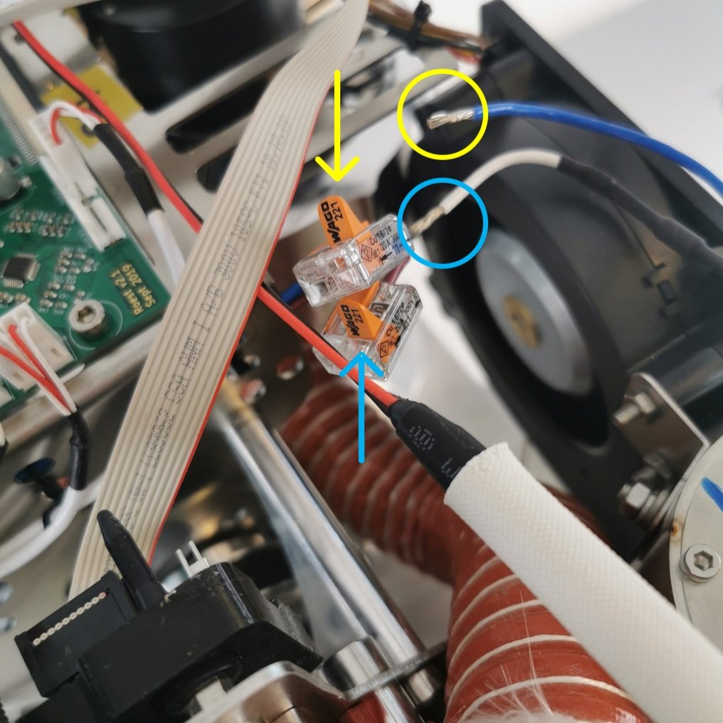
Only open the two flaps that read Wago 221.
6. Remove the heating system.
Undo the two bolts for the heating element.

Remove the heating element.

Undo one bolt loosely (don’t remove) on the inside of the heating element housing.

Undo two bolts loosely on the outside of the heating element housing, but don’t remove them. You can remove the orange hose to see better.

If you look inside the housing, it should look like this.

Pull the housing backward, so it slides away from the bolts holding it.

Pull the heating element housing with the heater fan upwards.

What it should look like after you pulled the housing off.
7. Install the new heater fan onto the old heating element housing.

The heating system you removed from the roaster should look like this.

Undo these two screws using a 2.5-millimeter hexagonal key. Hold a finger or on the back to keep the screw from spinning.

Use a spanner to hold the nut in place.

Use the spanner on the nut while undoing the screw from the other side.
Save your screws and nuts from the old heater fan; you will need them for the new one.

Cut the silicone on all sides where the fan and housing meet.

Pull the fan and housing apart.

Your old heater fan should be separated from the heating element housing at this point.

Find your new heater fan.

The orientation of the heater fan in relation to the heating element housing should be as shown in the photo above. There is a slot in the heater fan where the housing can be inserted.

Slide the housing inside the heater fan.

Insert the screws you removed from the old fan.

Turn your fan around (watch the screws so they don’t fall out).

Place the washers.

Place the nuts.

Find your spanner again to tighten the nuts.

Tighten the screws.

You need to use both your spanner and hexagonal key simultaneously.

You will need some silicone. We should provide it if you purchased a heater fan in our webshop.

You will need plastic gloves as well. Cut a hole at the tip of the bag to make a piping bag.

Use the piping bag to add silicone where the heater fan meets the heating element housing.

Add silicone to all sides.


Smear it out with your finger, removing excess silicone.


Make sure the area around the heating element stays clean.
8. Wait 24 hours for the silicone to dry.
9. Install the new heater fan system onto the roaster.

Slide the heating system onto the inlet housing.

Then push the heating system into place.

When your system has slid into place, it will look like this inside. If your mica tube is in the way, you can remove it.

Tighten the bolt inside and the two bolts on the outside. Install the mica tube if you removed it.
10. Install the heating element and connect it to the correct wago connectors (look at the image at the beginning of the guide for reference). Use a 2.5-millimeter hexagonal key to tighten the bolts.


Note the orientation of the heating element. The red rubber component should be closer to the PCB.
11. Install the drum and inlet temperature sensors if you have them:

Pull the cable through the bottom hole.

And then pull it through the top hole again.

Pull it through all the way, but not too tightly.

Make a note of the colors of the wires: Yellow is positive, and red is negative.

Make a note of the orientation on the terminal. Ensure the yellow wire goes into the positive terminal and the red wire goes into the negative terminal.
Ensure the cable is not in the way or hanging too loosely in the machine.
Do the same for the inlet temperature; insert it into the left screw terminal instead.
12. Connect the heater fan to the PCB (refer to the beginning of this guide if you are unsure of where).
13. Install back the front décor plate. Instructions here.
14. Install back the side panels. Find instructions here.
15. Install back the top plate following this guide.
16. Plug the roaster in, turn it on and test the heater fan. If it doesn’t work, contact the ROEST support team.
How to change: Touch Screen
How to replace a touch screen on your ROEST.
Where to buy touch screen?
If you are sure your touch screen is broken (you have talked to our Support Team) visit our e-shop to purchase a new one!
Note: sometimes touchscreen appears broken when there might be an issue with your firmware. Make sure to discuss your problem with our team.
Before you start
⚠️DISCLAIMER
Information in this document is believed to be accurate and reliable. However, the manufacturer does not give any representations or warranties, expressed or implied, as to the accuracy or completeness of such information and shall have no liability for the consequences of the use of such information. The manufacturer is not liable or responsible for any problems arising from the attempted repair. The manufacturer reserves the right to make changes to information published in this document, including without limitation specifications and product descriptions, at any time and without notice. The manufacturer's products are not designed, authorized, or warranted to be suitable for use in applications where failure or malfunction can reasonably be expected to result in personal injury, death, or severe property or environmental damage. The manufacturer accepts no liability for inclusion and/or use of its products in such equipment or applications and therefore such inclusion and/or use is for the customer’s own risk.
⚠️SAFETY INSTRUCTIONS
make sure the roaster is turned off
the power cord has to be unplugged
follow the steps as instructed below
Tools

2-millimeter hexagonal tool

Flat head screwdriver
*Use a screwdriver with a small width - to remove the screen from the front décor plate.
Parts
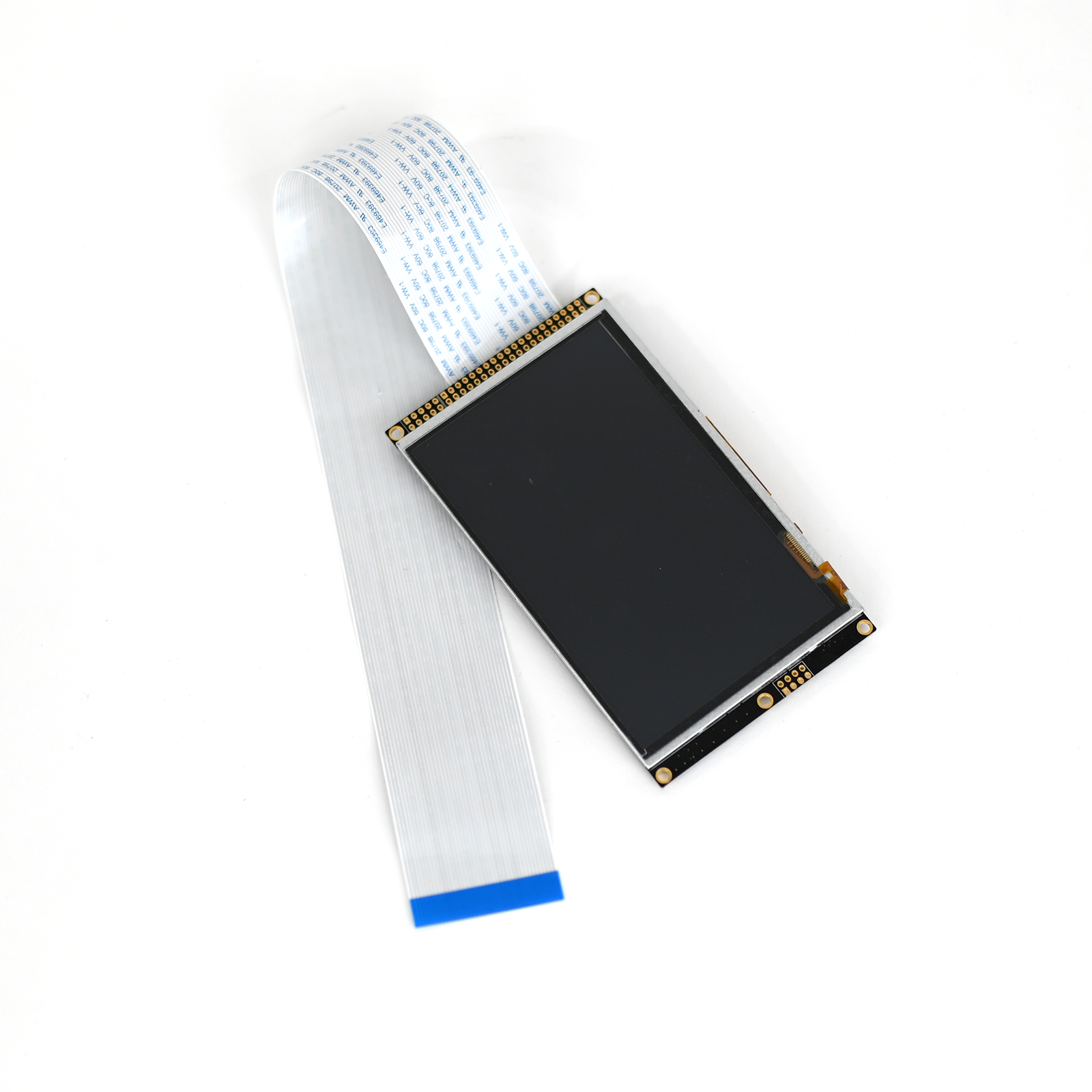
These are the parts you will receive when buying a new touchscreen:
Touch screen assembly
40-pin screen cable

Touchscreen assembly is made up of:
1. Screen
2. Screen bracket
3. Five off M3x6 Cap Head Screws

Front

Back
Instructions
Step-by-step guide:
1. Take off the top plate (remove the hopper before you start).
2. Pull out the trier and the drop handle.

A set screw attaches the black drop handle. Use the 2-millimeter hexagonal tool to remove it.
For a wooden drop handle, pull it to take it off.
3. Disconnect the 40-pin cable for the screen from the PCB.

Push back the black retaining clip and detach the cable. Ensure the retaining clip is left in place at the connection point.
4. Remove the three front plate screws.

Remove these three screws on the front with the 2-millimeter hexagonal tool.
5. Remove front décor plate from roaster slowly.

Take off the front décor plate and place it on a protective surface. Leave the 40-pin cable connected to the screen.
6. Remove the screen screws that attach the screen to the front plate by using the 2-millimeter hexagonal key.

7. Flip the front plate over and, using the flat-head screwdriver, pry the screen off the plate (held in place by white glue).

8. Install the 40-pin cable in the new touch screen. Push the black retaining clip and insert the cable (the blue band of the cable must face upwards). Once in position, fasten it by pushing the clip back to its original position.

Ensure that the cable has been pushed in as far as possible.
9. Peel off the removable plastic film.

10. Attach the screen to the front décor plate. Locate the touchscreen assembly and cable in the original location of the front décor plate.

Locate the touch screen and cable in the original location of the front plate.

Fasten it in place with two off M3 x 6 countersunk screws.
11. Feed the cable through the original slots on the roaster and put the front décor plate back in its position.

1. Slot in the front

2. Front décor plate installation

3. Cable through second slot
12. Install the 40-pin cable into the PCB. Push the black retaining clip and insert the cable (you must twist it to show the blue band of the cable facing up).

You can use the screwdriver to keep the clip “open” while inserting the cable.

Once in position, fasten it by pushing the clip back to its original position.
13. Install three off M3 x 6 countersunk screws into the front décor plate.


14. Install the top plate and the hopper.
Follow this order to tighten the screws
Make sure you press the front plate when installing screw 1 and 3
15. Install the drop handle and the trier. For a wooden drop handle, push it through. For a black drop handle, install the set screw by using the 2-millimeter hexagonal tool.

16. Plug the roaster in, turn it on and test the touchscreen. If it doesn’t work, contact the ROEST support team.
How to install: Conversion Kit
Here are the instructions on how to use your conversion kit.

Different Conversion Kits
Machines with a production number of P16_900 or higher can be converted to any voltage. For older machines, conversion is only possible when your machine was originally wired as 115v or 100v.
CONVERSION KIT TO 115V
IMPORTANT Difference: 115V VS 230V FUSE
CONVERSION KIT TO 230V
Where to buy Conversion Kit?
Are you interested in purchasing a Conversion kit? Visit our eshop! Note: Conversion is only possible when your machine is wired as 115v or 100v.
Before you start
⚠️DISCLAIMER
Information in this document is believed to be accurate and reliable. However, the manufacturer does not give any representations or warranties, expressed or implied, as to the accuracy or completeness of such information and shall have no liability for the consequences of the use of such information. The manufacturer is not liable or responsible for any problems arising from the attempted repair. The manufacturer reserves the right to make changes to information published in this document, including without limitation specifications and product descriptions, at any time and without notice. The manufacturer's products are not designed, authorized, or warranted to be suitable for use in applications where failure or malfunction can reasonably be expected to result in personal injury, death, or severe property or environmental damage. The manufacturer accepts no liability for inclusion and/or use of its products in such equipment or applications and therefore such inclusion and/or use is for the customer’s own risk.
⚠️SAFETY INSTRUCTIONS
make sure the roaster is turned off
the power cord has to be unplugged
follow the steps as instructed below
CONTENTs OF THE KIT
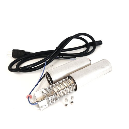
2x Heating element (230v or 115v)
Power cord
2x Fuse (230v or 115v)
TIME
5 - 10 minutes
TOOLS
hex keys (included in package with ROEST sample roaster)
Important
For machines with production numbers lower than P16_900, conversion is only possible when your machine was wired as 115v or 100v.
To check if your machine was wired as a 115V, see the roaster’s label with the name and production number. It will say Px_xxx 115v or 110v or Px_xxxC .
Heat distribution remains the same on 230v and 115v.
Instructions
To convert your roaster to the desired voltage, there are two sets of instructions you need to complete:
Changing the heating element and
Changing the fuse (see the guides below).
Make sure your roaster is turned off and unplugged before you begin.
I. part: Changing heating element

II. part: Changing fuse
After you have changed your heating element and replaced the correct fuse, you are ready to go!
How to change: Fuse
How to replace a fuse on your ROEST.

Notice the difference between the fuses.
Types of fuses
There are two types of fuses based on voltage: 115V and 230V.
Important: Make sure to use the correct type of fuse. See the difference in the photo above.
Where to buy fuse?
Are you out of fuses? Visit our e-shop to purchase a new one! Note: see the instructions below - there is one spare fuse inside your roaster.
Before you start
⚠️DISCLAIMER
Information in this document is believed to be accurate and reliable. However, the manufacturer does not give any representations or warranties, expressed or implied, as to the accuracy or completeness of such information and shall have no liability for the consequences of the use of such information. The manufacturer is not liable or responsible for any problems arising from the attempted repair. The manufacturer reserves the right to make changes to information published in this document, including without limitation specifications and product descriptions, at any time and without notice. The manufacturer's products are not designed, authorized, or warranted to be suitable for use in applications where failure or malfunction can reasonably be expected to result in personal injury, death, or severe property or environmental damage. The manufacturer accepts no liability for inclusion and/or use of its products in such equipment or applications and therefore such inclusion and/or use is for the customer’s own risk.
⚠️SAFETY INSTRUCTIONS
make sure the roaster is turned off
the power cord has to be unplugged
follow the steps as instructed below
Instructions
Below is a step-by-step guide on how to change a broken fuse or if converting between voltages.

1. Here, you can find the fuse. Open it using a hex key.

2. Pull it out.

3. Take it all the way out.

4. The fuse on the photo is a spare fuse. It is not in use when placed in this position. You don’t need to replace it.

5a. This is the fuse you need to change if broken or converting your machine to 230V.

5b. This is the fuse you need to change if broken or converting your machine to 115V.

6. Place the fuses back in the roaster.

7. Push in until it clicks.
You are ready to go!
How to change: Heating Element
Instructions on how to replace your heating element.

When to replace Heating Element
When your roaster is not heating up even though you closed the drum, the power is dropping or simply not increasing - your heating element could be broken. Read through this article first to check if your heating element needs to be replaced. If you’re having repeated problems with your heating element, read through this post on heating elements and their lifetime.
Important
We designed the roaster to be very responsive even with low airflow. This gives the operator the extra freedom to create his preferred profile, but it can cause some challenges for the heating element as it will operate at a higher temperature. Our heating elements are hand-made using only the best materials we could source, but there can still be variables that reduce the lifetime of the heating elements. To compensate, we made the heating elements easy to change. It’s also possible to increase the speed of the heat fan via the service menu. This will have a positive effect on the service life of the heating element.
Where to buy Heating Element
Your spare heating element was sent along with your ROEST. If you don’t have another spare one, you need to place your order.
Before you start
⚠️DISCLAIMER
Information in this document is believed to be accurate and reliable. However, the manufacturer does not give any representations or warranties, expressed or implied, as to the accuracy or completeness of such information and shall have no liability for the consequences of the use of such information. The manufacturer is not liable or responsible for any problems arising from the attempted repair. The manufacturer reserves the right to make changes to information published in this document, including without limitation specifications and product descriptions, at any time and without notice. The manufacturer's products are not designed, authorized, or warranted to be suitable for use in applications where failure or malfunction can reasonably be expected to result in personal injury, death, or severe property or environmental damage. The manufacturer accepts no liability for inclusion and/or use of its products in such equipment or applications and therefore such inclusion and/or use is for the customer’s own risk.
⚠️SAFETY INSTRUCTIONS
make sure the roaster is turned off
the power cord has to be unplugged
follow the steps as instructed below
TIME
5 - 10 minutes
TOOLS
hex keys (included in package with ROEST sample roaster)
How to replace Heating Element - Instructions
1. Remove the top plate. Watch the video to see how to remove the top plate.
2. Replace the heating element.
3. Install back the top plate. Watch the video to see how to install the top plate.
How to change: Proximity sensor - charge handle
Instructions on how to replace your charge handle proximity sensor.
If your roasting process does not start when pulling the charge handle, or you have a warning message on the screen (charge handle open) when the charge handle is resting in its place, your proximity sensor could be broken.
HOW TO DETERMINE IF A PROXIMITY SENSOR IS BROKEN:
Remove the top plate so you can see the sensors.
Move the charge-handle to see if a red light flashes on the sensor. If it does, it works.
If there is no red light, try to move the proximity sensor closer to the charge-handle using a 12-millimeters spanner.
Check the connection on the PCB, ensuring that the cable hasn’t been pulled off or isn’t properly plugged in.
Check that the proximity sensors for the drop and charge handle haven’t been swapped.
If none of the above fixes it, your proximity sensor is broken. Buy a new one or contact support if your machine is still under warranty.
Where to buy Proximity Sensor
Your spare universal proximity sensor was sent along with your ROEST. If you don’t have a spare one, you need to place your order.
Before you start
TIME
5 - 10 minutes
TOOLS
2-millimeters hex keys (included in the package with ROEST sample roaster)
12-millimeters spanner
SAFETY INSTRUCTIONS
make sure the roaster is turned off
power cord has to be unplugged
follow the steps as instructed below
Instructions
Follow the steps below:
Remove the top plate using the 2-millimeters hex keys.
Using the 12-millimeter spanner, remove the proximity sensor in front of the charge handle. In order to remove the sensor from the machine you will have to undo the cable ties holding the proximity sensor cable in place.

There is no correct order to how they must be tied together; the primary purpose is to keep the cables neatly in place and out of danger of getting damaged. You may notice we’ve tied some cables with loops before fastening them. This is useful when you have to change the PCB, making it possible to unfasten the components from the PCB without undoing the cable ties. You can use the photo above as a reference when tying the cables again. The pictures below show the trajectory of the cables from the drop and charge handle proximity sensors.


Above: The two cables can be positioned between the two components, like in the photo.
To the right: The positions of the proximity sensors on the PCB.

When the faulty proximity sensor has been removed, the new one must be installed. The proximity sensor comes with two nuts with a sawtooth pattern on one side. The direction of one of these nuts must be changed, so the sawtooth pattern faces the other way, as shown in the photos below.

The new proximity sensor will come with the nuts facing each other with their sawtooth pattern.

Rotate the nut closest to the end, so the sawtooth pattern faces toward the end instead of the other nut.
When installing the new sensor, you have to make sure it doesn’t interrupt the trajectory of the charge handle, which can make the handle hard to move and destroy the new sensor.

The sensor must not be in the way of the charge handle but must, at the same time, not be installed too far away for it to register the charge handle moving.
The best way to correct the distance is to pull the charge handle up to cover the hole to the proximity sensor. You then insert and screw in the proximity sensor until it can go no further in. The distance is good if the charge handle can fall down again without any issues.
Pull the handle up, and install the proximity sensor with a 12-millimeter spanner. Both nuts should be tightened firmly but not overly tight.
Tie the new proximity sensor with cable ties so it’s collected neatly, like in the photo below.

How to replace the Proximity Sensor - video
Troubleshoot for the Proximity sensor drop handle: How to tell if it’s broken and install it correctly.
You’re ready to go!
How to change: Proximity sensor - drop handle
Instructions on how to replace your drop handle proximity sensor.
If your roaster is not heating up (read here first) or there is a warning message on the screen (hatch open) when you move the drop handle to the downwards position, your proximity sensor could be broken.
HOW TO DETERMINE IF A PROXIMITY SENSOR IS BROKEN:
Remove the top plate so you can see the sensors.
Move the drop handle to see if a red light flashes on the sensor. If it does, it works.
If there is no red light, try to move the proximity sensor closer to the drop handle using a 12-millimeters spanner.
Check the connection on the PCB, ensuring that the cable hasn’t been pulled off or isn’t properly plugged in.
Check that the proximity sensors for the drop and charge handle haven’t been swapped.
If none of the above fixes it, your proximity sensor is broken. Buy a new one or contact support if your machine is still under warranty.
Where to buy Proximity Sensor
Your spare universal proximity sensor was sent along with your ROEST. If you don’t have a spare one, you need to place your order.
Before you start
⚠️DISCLAIMER
Information in this document is believed to be accurate and reliable. However, the manufacturer does not give any representations or warranties, expressed or implied, as to the accuracy or completeness of such information and shall have no liability for the consequences of the use of such information. The manufacturer is not liable or responsible for any problems arising from the attempted repair. The manufacturer reserves the right to make changes to information published in this document, including without limitation specifications and product descriptions, at any time and without notice. The manufacturer's products are not designed, authorized, or warranted to be suitable for use in applications where failure or malfunction can reasonably be expected to result in personal injury, death, or severe property or environmental damage. The manufacturer accepts no liability for inclusion and/or use of its products in such equipment or applications and therefore such inclusion and/or use is for the customer’s own risk.
⚠️SAFETY INSTRUCTIONS
make sure the roaster is turned off
the power cord has to be unplugged
follow the steps as instructed below
How to replace Proximity Sensor
TIME
5 - 10 minutes
TOOLS
2-millimeters hex keys (included in the package with ROEST sample roaster)
12-millimeters spanner
Instructions
Follow the steps below:
Remove the top plate using the 2-millimeters hex keys.
Using the 12-millimeter spanner, remove the proximity sensor in front of the drop handle. In order to remove the sensor from the machine you will have to undo the cable ties holding the proximity sensor cable in place.

Note: There is no correct order to how they must be tied together; the primary purpose is to keep the cables neatly in place and out of danger of getting damaged. You may notice we’ve tied some cables with loops before fastening them. This is useful when you have to change the PCB, making it possible to unfasten the components from the PCB without undoing the cable ties. You can use the photo above as a reference when tying the cables again. The pictures below show the trajectory of the cables from the drop and charge handle proximity sensors.


Above: The two cables can be positioned between the two components, like in the photo.
To the right: The positions of the proximity sensors on the PCB.

When the faulty proximity sensor has been removed, the new one must be installed. The proximity sensor comes with two nuts with a sawtooth pattern on one side. The direction of one of these nuts must be changed, so the sawtooth pattern faces the other way, as shown in the photos below.

The new proximity sensor will come with the nuts facing each other with their sawtooth pattern.
Rotate the nut closest to the end, so the sawtooth pattern faces toward the end instead of the other nut.
When installing the new sensor, you have to make sure it doesn’t interrupt the trajectory of the charge handle, which can make the handle hard to move and destroy the new sensor.

With the drop handle sensor, you must use your eyes to ensure the correct distance. You know it’s close enough if you turn on the machine, move the drop handle down, and see the light flashing on the sensor. The drop handle should also be smooth moving and not touching the sensor.
Tie the new proximity sensor with cable ties, so it’s collected neatly, like in the photo below.

How to replace the Proximity Sensor - video
You’re ready to go!
Touchscreen warning messages
Sections:
About Warning Messages
Warning messages are to help you diagnose an issue with your roaster. See below to learn why the different warning messages appear.
Hatch Open
This message is connected to the inductive sensor related to the drop handle door. It tells you that the drop handle is in the upward position. The message will show up when the drop handle is moved away from the inductive sensor (the sensor detects movement in front of it when the drop door is closed).
Something could be wrong if:
You still get this message when moving the drop handle to the downward position; your proximity sensor could be broken. The result is the roaster not heating up.
How to determine if a proximity sensor is broken:
Remove the top plate so you can see the sensors.
Move the drop or charge handle to see if a red light flashes on the sensor. If it does, it works.
If there is a red light flashing constantly, the sensor is broken.
If there is no red light, try to move the proximity sensor closer to the drop or charge handle using a 12-millimeters spanner.
Check the connection on the PCB, ensuring that the cable hasn’t been pulled off or isn’t properly plugged in.
Check that the proximity sensors for the drop and charge handle haven’t been swapped.
If none of the above fixes it, your proximity sensor is broken. Buy a new one or contact support if your machine is still under warranty.
Charge Handle Open
This message shows up when the charge handle is lifted (hence, movement is detected in front of the proximity sensor).
Something could be wrong if:
You get this warning message without lifting the charge handle/with the charge handle in the resting position.
The roasting process does not start when lifting the charge handle (and no warning message appears).
The proximity sensor could be faulty (sometimes malfunctioning due to too much heat), or the two proximity sensors for the drop and charge handle have been switched around. If the proximity sensor is broken, tapping charge in the top left corner can start the roasting process instead.
How to determine if a proximity sensor is broken:
Remove the top plate so you can see the sensors.
Move the drop or charge handle to see if a red light flashes on the sensor. If it does, it works.
If there is a red light flashing constantly, the sensor is broken.
If there is no red light, try to move the proximity sensor closer to the drop or charge handle using a 12-millimeters spanner.
Check the connection on the PCB, ensuring that the cable hasn’t been pulled off or isn’t properly plugged in.
Check that the proximity sensors for the drop and charge handle haven’t been swapped.
If none of the above fixes it, your proximity sensor is broken. Buy a new one or contact support if your machine is still under warranty.
Bean Dropper Error
This error appears when the machine tries to open the drop door, but the sensor can not detect that the door has opened.
Most commonly this means that the proximity sensor is not working properly, and needs to be adjusted or replaced, by following this guide. If the error was caused by a sensor issue, then the drop door will still open and release the beans.
If the drop door does not open, then the problem is the drop door motor. Contact support for help.
Chassis Fan Failure
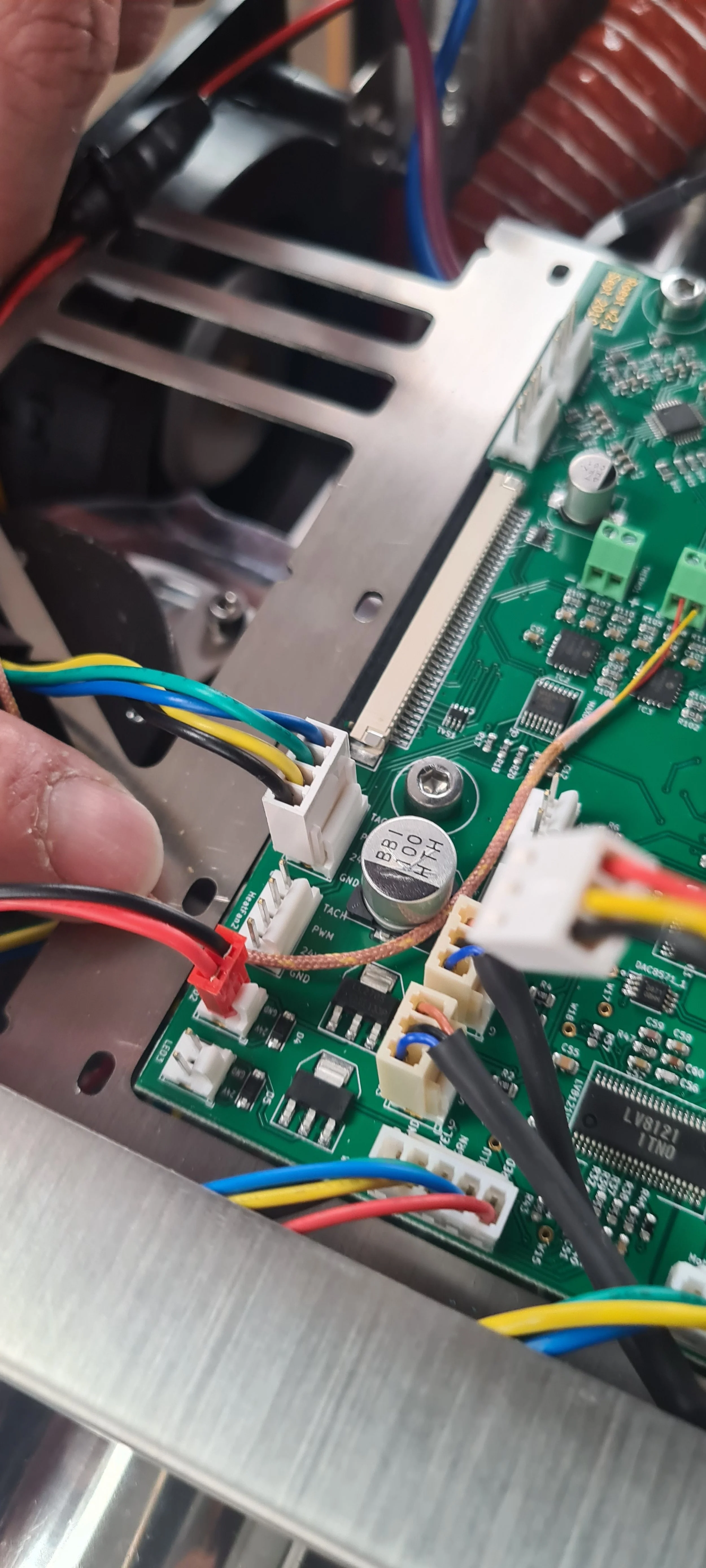
Related to the chassis fan behind the mesh grid at the back of the roaster. This is cooling the electronics of the roaster. If you get this message, first check your chassis fan settings. The warning message will appear when the fan’s speed is detected to be under 2000 RPM, so check to see if the ventilation fan (RPM) settings in the service menu have been lowered somehow. If not, you need to remove the top plate and check the following:
Connection from cable to PCB. Is the cable properly attached to the PCB? Check that all three pegs are correctly in. Use this photo for reference.
Turn off your roaster and inspect the extension cable connection. Is the extension cable properly connected to the fan cable? This can loosen over time; make sure the cable is firmly connected, and all pegs are correctly attached. Remove the extension cable and insert it again.
Check that the fan is running. It is easiest to see if you turn the roaster on and off. You can see it from above, looking inside the roaster or through the fan gritter at the back.
Troubleshoot a potentially broken fan:
Enter the service menu and tap “Debug hardware.”
Check the RPM value reading from “Chassis fan measured RPM.”
If there is a problem with the fan, the value would be NaN or 0. The normal condition would be around 2500.
If both the chassis and heater fan are displayed as NaN or 0, please contact Support, as this may indicate that you need a new fan chip on your PCB.
If the chassis fan is displayed as NaN/zero, but the heater fan is normal (around 3500 RPM), the next step is to determine if a problem with the fan causes this. Please turn off the roaster, unplug the power cord, and remove the top plate. Take off both the heater and chassis fan connectors from the PCB. Attach the chassis fan connector on the heater fan slot and the heater fan connector on the chassis fan slot.
Put the top plate on again (no need to fasten it yet), plug in the power cord, and turn the machine back on. Reenter the service menu and the debug area.
If there is a problem with the chassis fan: the heater fan should now display NaN/0. You need to order a new Chassis fan and replace it if it does.
If the values on the Debug area remain the same (the chassis fan is NaN/zero, and the heater fan displays typical values), there is something wrong with the chip on your PCB. Contact Support with the following message: The chassis fan is shown as NaN/zero in the Service menu. Changing the fan setup (chassis fan connector on heating fan chip and vice versa) does not change the readout, and a replacement PCB or repair of the PCB is required.
Heater Fan Failure
Related to the heater fan on the right-hand side of the roaster. The warning message shows up if the speed drops below 3000 RPM, so check your settings to see that it hasn't been lowered somehow. If the settings are ok, you need to remove the top plate and check the following:
Check the cable connection on the PCB. Is the cable properly connected, with all pegs fi rmly attached in the holes?
Troubleshoot a potentially broken fan:
Enter the service menu and tap “Debug hardware.”
Check the RPM value reading from “Heater fan measured RPM.”
If there is a problem with the fan, the value would be NaN or 0. The normal condition would be around 3400.
If both the chassis and heater fan are displayed as NaN or 0, please contact Support, as this may indicate that you need a new fan chip on your PCB.
If the heater fan is displayed as NaN/zero, but the chassis fan is normal (around 2500 RPM), the next step is to determine if a problem with the fan causes this. Please turn off the roaster, unplug the power cord, and remove the top plate. Take off both the heater and chassis fan connectors from the PCB. Attach the chassis fan connector on the heater fan slot and the heater fan connector on the chassis fan slot.
Put the top plate on again (no need to fasten it yet), plug in the power cord, and turn the machine back on. Reenter the service menu and the debug area.
If there is a problem with the heater fan: the chassis fan should now display NaN/0. You need to order a new heater fan and replace it if it does.
If the values on the Debug area remain the same (the heater fan is NaN/zero, and the chassis fan displays typical values), there is something wrong with the chip on your PCB. Contact Support with the following message: The heater fan is shown as NaN/zero in the Service menu. Changing the fan setup (chassis fan connector on heating fan chip and vice versa) does not change the readout, and a replacement PCB or repair of the PCB is required.
Exhaust fan failure
This warning message is triggered if the exhaust fan’s motor stops spinning. If you get this message, check the following:
Cool down the roaster completely, and remove the ventilation hose from the back so you can see into the exhaust ventilation exit. You should be able to see the impellers from there. Turn the roaster on and off to see if the impellers are spinning around. The warning message is related to the impellers on the left-hand side. The right-hand side impellers will affect bean cooling but have no warning message on-screen.
Contact support to get a new motor if your impellers are not spinning.
Motor is Stuck
This warning message is related to the inductive sensor monitoring the chamber motor rotation. The message is triggered if the proximity sensor detects that rotation is too slow according to a calculation based on the expected speed of the motor and the motor gear ratio.
First, check your motor gear ratio settings in the service menu; it should say 12:1 unless you have an older machine (p16_30 and earlier models). If you have an older model, check your correct setting here.
- If your drum moves back and forth, the proximity sensor is most likely placed too far away from the RPM plate and needs to be adjusted. You can use this guide for reference, but move it closer to the RPM plate instead of changing the sensor.
Please also check out our troubleshooting guide for motor/paddle issues.
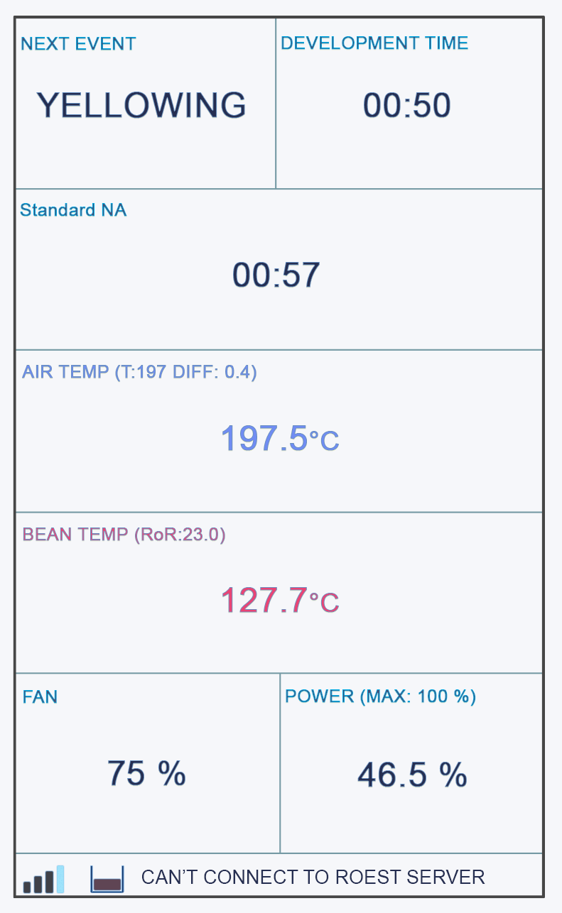
Can’t connect to the ROEST server
This warning message is triggered if the machine is unable to connect to the MQTT server (roest server). This can happen if the wifi network of the machine has a bad internet connection or our server is down. Most of the time, it is not related to anything wrong with the device.
Max Temperature Reached
This warning message is triggered if the ET sensor reads a temperature of 320 degrees or more.
Machine is too hot! Restart!
This message is triggered by the PCB becoming too hot (if the temperature sensor on the PCB reports 65 degrees or more). Reasons:
The chassis fan gitter needs to be cleaned. If too much dirt and grit have been collected in the fan gitter, the chassis fan won't be able to do its job correctly. Make sure to clean the fan gitter regularly.
Warning message combined with chassis fan error: Go back to the checkpoint for the chassis fan warning message.
Remove the top plate and check the orange hose from the chamber to the back of the roaster to see if it is damaged or not correctly attached to both ends (perhaps leaking heat somewhere?).
Fan Error Detected! Restart!
This message will be triggered along with chassis fan failure, heater fan failure, and exhaust fan failure warning messages.
No server connection
When you get this message on the screen the roaster is still connected to your wifi but the connection to the internet / our server is disrupted. If the roaster manages to connect within 60 seconds then this message will disappear - if it takes longer then the message will stay active to notify you. As long as the roaster manages to connect within 2 minutes then the log will be updated. If this message often appears then your wifi connection is bad or the internet connection is unstable.
Warning WiFi connection lost.
When you get this message on the screen, the roaster has lost the internet connection (or has spent more than 10 seconds trying to connect during startup. If the roaster manages to connect within 60 seconds, this message will disappear - if it takes longer, it will stay active to notify you. You can then see if the wifi symbol is stable at the lower left corner. As long as the roaster connects within 2 minutes, the log will be updated. If this message often appears, then your wifi connection is bad, or the internet connection is unstable.
Important safeguards
When using electrical appliances, basic safety precautions should always be followed, including the ones below.
Sections:
General
1. Read all instructions carefully before using the appliance.
2. The roaster is only intended for commercial use.
3. Incorrect operations and improper use can damage the appliance and cause injury to the user.
4. Do not touch hot surfaces. Use handles or knobs.
5. To protect against electrical shock, do not immerse the cord, plugs, or roaster in water or other liquids.
6. Always turn off the power button and unplug from the outlet when not in use and before cleaning. Allow to cool before turning off.
7. Using accessory attachments or software not recommended by the appliance manufacturer may cause injuries, fire, or electric shock.
8. Do not use outdoors.
9. Do not let the cord hang over the edge of the table or counter or touch hot surfaces.
10. Do not place on or near a hot gas or electric burner or in a heated oven.
11. Always attach the plug to the appliance first, then plug the cord into the wall outlet. To disconnect, turn any control to OFF, then remove the plug from the wall outlet.
12. Do not use appliances for other than intended use.
13. The roaster operates at high temperatures and must be kept away from flammable materials, including chemicals, fabrics, and paper.
14. The roaster must be placed on a heat-resistant, slip-proof surface that will not allow the roaster to slide.
15. Allow 20cm of space around the sides and front of the roaster.
16. Never use the ROEST from within a cabinet.
17. Never leave the ROEST unattended during pre-heating and roasting. Also, do not leave the roaster unattended until 2 minutes after the cooling process has started to ensure no fire is present.
18. There is a risk of the coffee beans catching fire during roasting. Parts of the roaster also become hot enough to cause burns.
19. The fumes from roasting may be harmful. Please ensure adequate venting of smoke. Read all about ventilation here.
20. The instructions for cleaning the appliance must be followed.
21. The appliance must not be operated using an external timer or separate remote-control system.
22. This appliance can be used by children aged eight years and above and persons with reduced physical, sensory or mental capabilities or lack of experience and knowledge if they have been given supervision or instruction concerning the use of the appliance in a safe way and understand the hazards involved:
• Children shall not play with the appliance.
• Cleaning and user maintenance shall not be done by children unless they are older than eight and supervised.
• Keep the appliance and cord out of reach of children under eight.
23. If the supply cord is damaged, it must be replaced by a special cord or assembly available from the manufacturer or its service agent.
24. If the ventilation sucks in coffee beans or any small object, they will be ejected (shot out) at high speed from the exit ventilation hole. Primarily this can happen through the cooling tray.
Therefore, the ventilation exit hole must never be directed against people, and a person must never look inside the ventilation exit hole when the roaster is on. We recommend always using at least a small ventilation hose to create a 90-degree angle.
25. This appliance is intended to be used in cupping labs, coffee shops, roasteries, households, and similar applications such as staff kitchen areas in shops, offices, and other working environments; - farmhouses; - bed and breakfast type environments.
26. Save these instructions.
One year guarantee
This product is guaranteed for one year from the date of purchase. If any defect arises due to faulty materials or workmanship, the defective products must be returned to ROEST for repair or replacement.
The following conditions apply:
The product must be installed and used per the instructions in this user manual.
The guarantee does not cover wear and tear, damage, misuse, or consumable parts.
ROEST Coffee AS has no responsibility for incidental or consequential loss or damage.
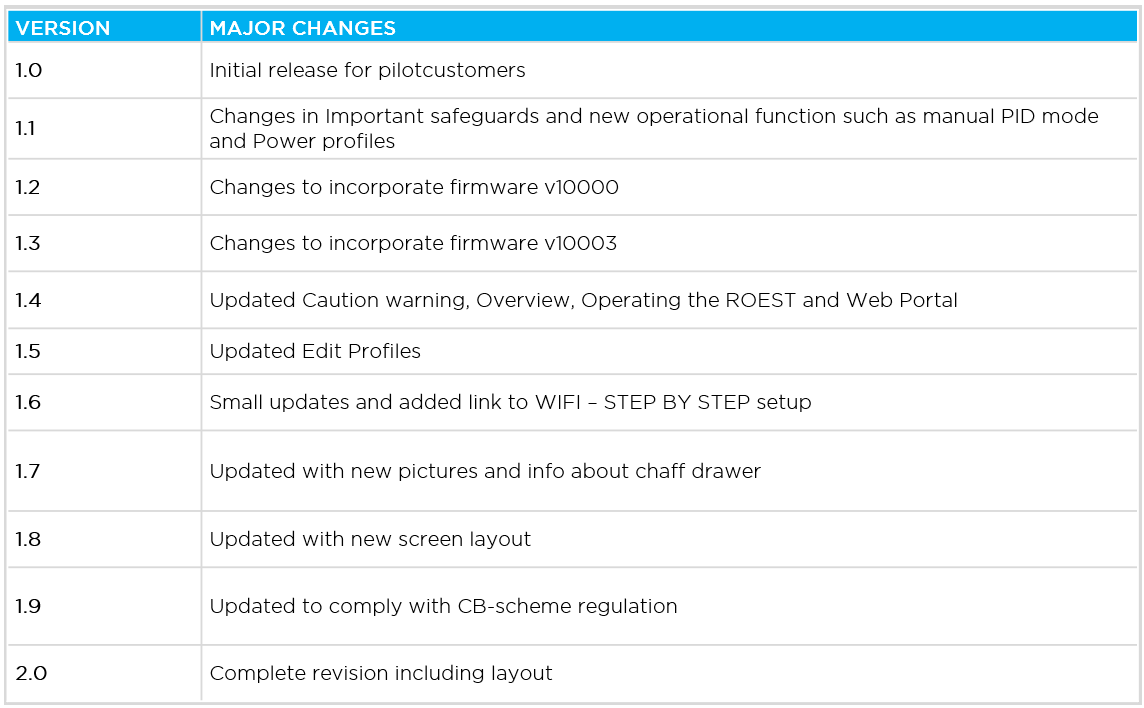
Revisions
Alterations services and accessories
1. Do not modify the roaster without permission from the producer.
2. Any accessories not recommended by the manufacturer must not change the operation of the coffee roaster or interfere with regular operation.
3. If disassembling is necessary, allow the machine to cool completely before service is carried out. Always disconnect the power plug before disassembling the roaster.
4. Do not operate the roaster if not fully assembled.
5. Do not operate the coffee roaster if it is damaged or you suspect a malfunction.
6. Do not attempt to service the roaster yourself unless instructed by us. Using accessory attachments other than those supplied or recommended by the manufacturer may cause hazards and void your warranty.
Electrical
1. To avoid electric shock, do not operate the roaster in a wet environment or near water. Any cleaning should be done with a moist or dry cloth and only be performed when the roaster is cooled down, and the power cord is disconnected. Some parts may be removed for additional cleaning.
2. The power cord and USB cord must be arranged in such a way that they will not be tripped over or able to pull the roaster off the table. Keep the cords away from the front part of the roaster, which may get very hot and can melt the wire.
3. The roaster needs a dedicated electrical circuit with ground (earth). Do NOT plug other appliances into this circuit.
4. If an extension cord is needed, please ensure it meets the minimum power rating requirements and is fully grounded (earthed). Do not connect other appliances to the cord.
Mechanical
1. Never touch moving parts; do not place hands or fingers inside the drum while the roaster is connected. This includes the trier hole, hopper, and the side where beans exit.
2. Never place hands or fingers inside the ventilation exit at the back. The fan has metal impellers that can create injuries.
3. The coffee roaster is heavy, and care should be taken when moving the roaster. Only move the roaster when it is completely cooled down. Do not lift the coffee roaster by the handles, chaff drawer, or other detachable parts.
Roasting
1. When coffee beans are dropped from the machine into the cooling tray, they are extremely hot and should not be touched until cooled completely.
2. The operating environment should be clean and free from dust and sand.
3. ROEST is only for roasting coffee beans. Roasting other food/items will void the warranty.
4. After roasting has finished, the roaster will return to “roasting standby mode” and be ready to roast another batch.
5. When roasting is done, please leave the roaster to cool down. Follow the instructions here.
6. Do NOT disconnect the power until properly cooled down, or you can risk damage.
7. The chaff drawer should be emptied after each roast session or every 25 roasts. Read the instructions here.
8. After about 500-1000 roasts, the roaster must be deep cleaned.
9. The roaster is designed for profile roasting, minimum of 5 minutes of roasting cycles. Meaning the temperature goes down to below 250 degrees Celsius between each roast. The roaster shall therefore not be used on maximum power in manual mode. If the environment temperature reaches 320 degrees Celsius, the electrical element will be turned off.
Adjustable roasting parameters
There are many parameters you can adjust before or during roasting. You will find some of them on the main touchscreen, the rest are located in ROAST SETTINGS.
Sections:
Main screen parameters
These are the adjustable parameters located on the main screen of your roaster.

1. DEVELOPMENT TIME. You can change the development time during the roasting process without switching to manual mode. Tap on DEVELOPMENT TIME and adjust the time using the rotary knob. Once “First Crack” is registered, the timer will start and cannot be changed. By tapping the countdown, you can cancel the auto drop and drop the beans when you want to.
2. AIR TEMPERATURE (ET).
This is the primary variable for adjusting a roast. The sensor sits in the upper mid-section of the drum. This temperature responds very rapidly to changes in heat input. If adjusting the ET, you will switch to manual mode (Manual ET Profile).
3. BEAN TEMPERATURE (BT) AND DRUM TEMPERATURE
Instant temperature measurement of the bean surface. Adjusting BT on the screen will not switch to manual mode. Instant measurements of the drum temperature are also visible below the BT temperature.
4. FAN.
The fan setting changes the speed of the exhaust fan. Note: If you have a fixed ventilation hose out of the room and smell roasted coffee, this can be because the exhaust fan setting is too low.
IMPORTANT: The higher the airflow, the more energy is used in temperature-based profiles. More increased airflow will have an impact on the roasting time. However, the effect is not as significant as you might have experienced with traditional open drum roasters. We suggest adjusting the temperature or power to adjust the total roasting time. We have roasted great coffee on both low and high airflow. It depends on the profile overall – and of course – the coffee.
5. POWER.
When controlling the power, any changes made to the power percentage on the screen is directly changing the power input to the heating elements. You will switch to manual mode if manually adjusting the power (Manual Power Profile).
Roast settings parameters
These are the adjustable parameters located in your roaster via ROAST SETTINGS.

1. REDUCE PWR AFTER FC.
If you roast using a Power profile, this setting can automatically reduce the power after a First Crack event has been registered.
For example: if the power setting in the profile is 80%, then a 10% reduction would mean that the power is reduced to 72% (10% of 80% power is eight percentage points).
Watch this video to learn more about this useful feature.
2. WAITING TEMPERATURE (charge temperature).
The starting air temperature for Power Profiles. You can set a preheat temperature when creating a profile as well, but if you wish to vary between batches, for example, you can leave that field blank and just adjust from the screen in between batches instead.
IMPORTANT: The waiting or charge temperature is set in the profile creator for temperature profiles. Depending on the profile, it can be beneficial to have a higher or lower starting temperature than the profile itself. A high charge temperature will increase the conductive heat transfer at the beginning of the roast, as the roasting chamber will store more heat. A lower charge temperature will help reduce energy consumption if the machine is idling for more extended periods between roasts and will also shift the heat transfer more towards convection in the beginning.
3. DEVELOPMENT (AUTO DROP) SETTING.
Choose between percentage (%) and seconds (SEC) for development time after First Crack. If percentage is used, the development time will be calculated from the total time.
4. MAIN MOTOR SPEED.
Manual adjustment of the drum speed. It can be adjusted at all times during a roast without switching to manual mode.
IMPORTANT: Changing the Main Motor Speed (RPM) of the paddles agitating the coffee will have a much more significant impact on the roast than changes made to the airflow. Initially, higher RPM equals a faster roast. With higher RPM, the coffee is “thrown” into the hot air and spread more evenly in the chamber. With higher RPM, the coffee will be exposed to the hot air more efficiently. Still, it will also impact the precision of the bean temperature sensor since the sensor will pick up hot air and bean surface temperatures.
5. BUZZER TEMPERATURE.
The buzzer will make a sound when a set bean temperature is reached. This is helpful if you do not want to miss, e.g., the First Crack event.
Watch the video below to see how to set up the Buzzer on your roaster.
6. YELLOWING BT THRESHOLD.
The bean temperature which must be reached for ROEST to mark a Yellowing event. Note: It is set at 175 degrees Celsius by default which is valid for a 100g profile. If you roast a different batch size, you should adjust it.
7. FIRST CRACK DETECTION.
If you have purchased a ROEST sample roaster with the FC detection system, tap ON to activate this feature. Here you can adjust the following parameters:
7.a. BT Threshold: Bean temperature that has to be reached in order for First Crack detection to start registering single cracks.
7.b.Trigger count: You can choose how many cracks are needed in order to register the First Crack event automatically. We recommend 3-5 cracks.

Parameters that will not affect automatic mode
The following parameters can be adjusted without switching to manual mode:
Development time
Fan
Reduce PWR After FC
Development time (Auto drop)
First Crack settings (BT threshold and Trigger count)
Main motor speed (RPM)
Parameters that will affect manual mode
If you are roasting in automatic mode, ROEST will switch to manual mode if you adjust the following parameters:
Air temperature
Power
However, the First Crack detection will not be affected if already active.
You can read more about roasting here.
-
Adjustable roasting parameters
Service menu - includes recommended settings for motor gear ratio, cooling fan, heater fan, and PID settings.
-